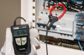
An uplifting experience is generally considered to be something positive, but not when it comes to loop impedance testing. But what exactly is uplift, why is it a problem, and what can be done about it? Peter Wade of Megger has the answers.
Recent editions of the IET Wiring Regulations have required almost all circuits to include not only overcurrent protection, but also earth leakage protection. For this reason, it is now common to find circuits that include an RCBO or an RCD connected downstream of an MCB. These arrangements can, however, give rise to problems when making non-trip loop impedance measurements. In simple terms, the instrument used to measure the loop impedance may include the internal impedance of the RCD or RCBO in the result. This is usually know as RCD uplift.
But does uplift really matter? Let’s look at a practical example. The loop impedance of a circuit must be low enough to ensure that the overcurrent protective device operates in the required time. The details are provided in the IEC 60364 standard and its UK equivalent. Taking just one example: for a normal 32 A Type B circuit breaker the loop impedance should be below 1.37 Ω. To provide a margin for error, the IET Wiring Regulations multiply this by 0.8, giving a maximum acceptable loop impedance of 1.1 Ω.
The uplift produced by a typical 30 mA RCD can be 0.5 Ω or more, which means that if the basic circuit resistance, as would be measured by a continuity test, is 0.7 Ω, a measurement carried out with a loop impedance tester would give a result of 0.7 Ω (the true circuit impedance) + 0.5 Ω (the uplift) = 1.2 Ω. On this basis, the circuit would fail the loop impedance test, even though its true impedance is only 0.7 Ω, which is well within the prescribed limit. To put it another way – yes, RCD uplift does matter!
It is important to note that uplift doesn’t occur with all types of RCD and RCBO. In fact, there is no easy and reliable way of deciding which devices will produce uplift and which won’t, and when uplift does occur, the actual amount of uplift can vary greatly between devices that are apparently the same.
When they experience RCD uplift, many users of electrical test equipment suspect that there is a problem with the instrument they’re using, but this is an incorrect conclusion. In fact, the instrument is correctly measuring the impedance in the circuit under test, under the conditions used in the test. Let’s explain. Fig 1 shows a typical circuit for an RCD.
Coils A and B create a magnetic flux in the ferrite core of the RCD. If the currents in the coils are equal, the fluxes produced by the coils cancel out. If the currents are different, however, the fluxes don’t cancel, and the sense coil C detects the difference. When the difference becomes large enough, the leakage current sense electronics operates the relay and disconnects the supply.
Note that it doesn’t matter how much current is flowing in the L-N circuit, it’s the difference between the L and N currents that trips the RCD. Because of this, we can omit the L and N currents in the simplified circuit shown in Fig 2, and show only the tiny L to PE test current – 15 mA – that’s used by the test instrument in a non-trip loop test.
In Fig 2, the phase conductor has an impedance of 0.3 Ω and the PE conductor has an impedance of 0.4 Ω. In theory the circuit would be expected to have a total of 0.7 Ω. However Coil A has an impedance of 0.5 Ω, which the instrument includes in the loop impedance measurement, as it cannot differentiate between conductor and coil impedances. Consequently a loop impedance of 1.2 Ω is reported. Once again it’s worth stressing that not all RCDs or RCBOs affect the loop impedance value but for those that do, this problem can be very confusing, annoying and time wasting.
So what can be done about this? Megger has been working toward a practical and convenient solution for this problem for many years and after much research and investment, it has developed one. The new Megger MFT1741 multifunction installation tester incorporates a three-wire non-trip loop test feature based on a new measuring technique that prevents the RCD coil from influencing the measurement, effectively eliminating RCD uplift, irrespective of the type of RCD or RCBO protecting the circuit. So the new method would return 0.7 Ω rather than the 1.2 Ω, in-line with the values reported by a continuity test.
The new measuring technique also offers other benefits, including a confidence display that saves time on electrically quiet circuits by allowing results to be obtained much more quickly than with standard instruments and also delivers high-confidence results on noisy circuits. In addition, for the first time, the new technique makes it possible to carry out non-trip tests on circuits protected with 10mA RCDs and RCBOs of the type often used in schools and other special locations.
There’s no doubt that RCD uplift can sometimes be a problem when carrying out low-current non-trip loop tests with a conventional instrument. But it’s a problem that contractors and others who test electrical installations no longer have to live with. There’s now an easy and convenient solution – simply buy one of the new multifunction testers that use measuring techniques specifically designed to eliminate troublesome uplift!
For more information about the MFT1741 multifunction installation tester from Megger visit: https://uk.megger.com


