NAPIT’s Bill Allan investigates two examples regarding the application of Table 54.8 within the 18th Edition.
The 18th Edition of BS 7671 introduced a small but significant change to Table 54.8 which has caused some to question how the table is to be applied.
In the 17th Edition of BS 7671, Table 54.8 stated that the minimum cross-sectional-area (csa) of the main bonding conductors must be related to the neutral of the incoming supply. Now in the 18th Edition, Table 54.8 requires the main bonding to be related to the PEN conductor of the supply.
This article will deal with two questions relating to this change.
A typical scenario
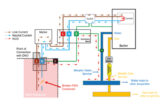
An electrical contractor is responsible for the design and installation of the electricity supply within a block containing twenty flats. The supply is TN-C-S (PME) and the incoming cable enters the building on the ground floor. The line and neutral conductors of the main tails from the cut-out to the meter each have a cross-sectional area (csa) of 70mm2.
At the intake position on the ground floor, the contractor can see the 70mm2 neutral conductor of the main tail coming out of the cut-out but, as the PEN conductor is not visible, the contractor cannot tell what size it is.
Each flat is supplied by a rising main with separate neutral and protective conductors (SNE). The line and neutral conductors have a csa of 25mm2 and the protective conductor has a csa of 16mm2.
Question 1:
Is the contractor to assume that the PEN conductor has the same csa as the neutral conductor in the main tail or must they enquire of the Distribution Network Operator (DNO) to ascertain the csa of the PEN conductor?
Question 2:
Should the main bonding within each flat have a csa which is related to the csa of the PEN conductor as Table 54.8 appears to require or to the csa of the neutral in the rising main?
A few general remarks
The current which each main protective bonding conductor will have to carry in the event of a fault – whether a line to Earth fault or a broken PEN conductor – cannot be known, except in the unlikely case of the relative impedances of all the paths to Earth being known. This means that the sizes for the main bonding conductors given in Table 54.8 are somewhat arbitrary.
However, due to the low earth fault loop impedance path of TN-C-S systems, any fault current is likely to be substantial and for this reason, Regulation 544.1.1 of BS 7671 requires a larger cross-sectional area for main bonding conductors in PME installations, compared to TN-S and TT installations. Consequently, main bonding conductors must be sized in accordance with the PEN conductor of the supply in PME installations.
Question 1 – the answer
The best advice is to contact the local Distribution Network Operator (DNO) as only they can know the csa of the PEN conductor. Besides, local network conditions may require larger conductors than those in Table 54.8 of BS 7671. For the telephone numbers of DNOs in your area, consult the article, Generation and Supply by Donald Holmes which was in Issue 3, 2017 of The Competent Person magazine.
Guidance on the sizing of main bonding conductors in PME supply systems is given in Table 4.9a of The Energy Networks Association (ENA) publication, Engineering Recommendation G12, Issue 4, Amendment 1, 2015 – Requirements for the Application of Protective Multiple Earthing to Low Voltage Networks. This table is reproduced below as Table 1.
Table 1 – Typical DNO incoming cable conductor sizes
 In addition, we would make the following general comments. The PEN conductor is unlikely to be visible and, even if it was, it could be difficult to establish its cross-sectional area (csa) by visual inspection alone. However, as the meter tails are visible, the csa of each tail may be able to be determined by visual examination. If so, it would seem reasonable to assume that the neutral conductor meter tail has the same csa as the PEN conductor (in this case, 70mm2).
If we were to make that assumption, then by using Table 54.8, this would give us a csa of 25mm2 for the main bonding conductors.
Nevertheless, the importance of consulting the DNO bears repetition as only they are in a position to be able to confirm whether the above premise is correct in this case.
Question 2 – the answer
Where a DNO has provided a multi-occupancy domestic block with a TN-C-S system (PME), and a different company, such as a Building Network Operator (BNO) is responsible for the rising mains, that company is not permitted to extend the PME system except where the one of the three conditions in Regulation 543.4. 2 has been complied with.
Assuming that the PME system cannot be extended, each rising main would consist of a line conductor, a neutral conductor and a protective conductor. In this case, the csa of the live conductors in the rising main to each flat is 25mm2 and the earthing conductor in the rising main is 16mm2.
As each flat is considered to be an, ‘installation’ by Regulation 411.3.1.2, main bonding is required within each flat. With Table 54.8 in mind, the question then arises – what size should these main bonding conductors be? To require that the main bonding at each flat be sized in accordance with the PEN conductor of the incoming supply to the building would mean installing main bonding conductors with a csa of 25mm2.
In our view, the main bonding conductors in each flat should be sized according to the neutral conductor of the rising main which, in this case, is 25mm2. Referring to Table 54.8, would mean main bonding conductors with a csa of 10mm2.
Get more NAPIT membership details and support by clicking here