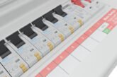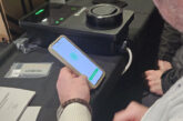
Pete (Monty) Monfort, Director of Arena Training Centre and Monty Electrics, takes an in-depth look at protecting yourself from electrical shocks.
Recently the industry has had a big push on promoting safe isolation, and quite rightly so when there are still individuals being killed from electric shocks every year.
Many of us are familiar with the useful safe isolation posters and best practice examples that are out there to guide us, but do you really understand the underlying complexities of safe isolation?
In this article I hope to provide some examples where just ‘blindly’ following the standard safe isolation procedure could still result in an electric shock.
Let’s start with the fundamentals first, though. For example, what equipment should we use to prove dead? GS38 HSE guidance recommends the use of a two-pole approved voltage indicator, but other test equipment still has its uses and can include volt pens, multi-meters and clamp meters.
Approved BS EN 61243-3:2014 two pole voltage indicator
These require a potential difference between the poles to detect anything, with approved indicators providing a one pole warning (which non-approved versions may not). These shouldn’t have fused leads (with user safety afforded by resistors in the leads instead) and they should work in the absence of a battery as well. Such devices are designed purely to test voltage and whilst you may think your MFT could do the same, unfortunately a user may select the wrong test and unwittingly receive a shock.
So, make sure you have a dedicated two pole voltage indicator to prove dead, which should be used in conjunction with a proving unit.
Single pole non-contact testers (volt pens)
These aren’t generally accepted as a method of proving dead but they are, in my opinion, useful tools nonetheless. Voltage is detected by way of the fluctuating electric field on an AC circuit and the operator forms part of a capacitively coupled AC circuit.
Be aware, though:
• The user must have a reference to ground, so you must be holding the tester. If you’re too high up a ladder, for example, the capacitive circuit could be broken, resulting in a failure to detect live parts.
• You should still prove the device on a known live circuit.
• DC voltage isn’t detected because the magnetic field isn’t fluctuating.
• They work on live conductors, even when there’s no load attached.
• They will not detect live conductors that are shielded by armourings, screens or metal cabinets or ducting. They will detect if the armourings are live, however.
• False lives can arise when you become capacitively linked to another live circuit that you might be unaware of. Single pole testers can have varying levels of sensitivity too and users need to be familiar with the ranges when using them.
Single pole contact testers (volt pens)
These work like their non-contact counterparts but are also not really accepted as a method of proving dead. They are generally considered more accurate than non-contact testers, however, since the user can physically contact the metal under test.
Clamp meters
These detect current flow in a conductor using magnetic induction and a hall sensor. Clearly these devices will not detect current flow if clamped around two opposing conductors such as line and neutral since the magnetic fields will cancel each other out. DC versions are available and if you’re working on solar systems these are recommended to ensure current flow is zero before connectors are disconnected.
All the gear, no idea?
Despite the fact you’ve equipped yourself with an HSE approved two pole tester with proving unit and carried out the isolation procedure, you could still be at risk of receiving a shock if you encounter a particular type of scenario. These include:
1. Diverted neutral conductors
Diverted Neutral current can occur if there’s a break in the protective earth and neutral (PEN) conductors in the distribution network. This can lead to dangerous voltages on the protective earthing system, including extraneous conductive parts.
Whilst you may be forgiven for thinking TT and TNS systems are unaffected, you would be wrong, since much of the distribution TNS network has become hybridised and should be considered TNCS for design and safety purposes. In any event, TNS and TT systems often share extraneous conductive parts with installations in which PME conditions apply.
A simple safe isolation procedure may prove the system dead when in fact, the system is energised across line, neutral and earth connections. A voltage indicator that indicates live energy with a single pole function is therefore essential to avoid a shock.
Guidance Note 3 Appendix D provides a detailed description of how to check for diverted neutral currents or you could check out episodes 77 and 92 of the E5 Group YouTube channel.
2. Alternative supplies
Alternative supplies are becoming more prevalent and isolating a board without consideration for a secondary supply might see you working on a circuit that has become live after a generator supply has been switched on.
Whilst you may assume generators such as invertors will switch off once AC supplies are isolated, this isn’t the case for systems that have the capacity to work in island mode. It’s essential that you fully examine the electrical installation and identify all points of supply ensuring that they’re correctly isolated and locked off.
Meter operatives have recently altered their standard operating procedures and now check that electric vehicles are disconnected since EVs are now being used as back-up generation in some properties.
3. Borrowed neutrals
Borrowed neutrals will be familiar to many domestic electricians who’ve swapped old domestic fuse boards for modern boards with RCDs, only to discover they can’t get the power to stay on due to upstairs and downstairs lighting circuits sharing a neutral.
In the case of a borrowed neutral two circuits are supplied via protective devices and the load on one circuit is connected to the neutral of the other, often out of convenience during wiring.
Isolation of one circuit can therefore lead to a dangerous situation where the circuit may prove dead but may be live or may become live during the work being undertaken. Isolating the entire board may eliminate the risk but consider the scenario where the neutral is supplied from a second board.
Operatives need to be fully aware of the wiring in the property and, when working in complex environments, test regularly during work or use circuit tracing technology to be confident that circuits do not share neutrals. The current AM2 assessment actually incorporates a check to ensure the operation of light switches on two-way circuits does not result in a circuit becoming live.
4. Capacitors
As a young lad I was always curious about how things worked and upon dismantling some electronic equipment which I had unplugged (I’m not stupid you know) I received a crack off a capacitor (but, yes, I might be ignorant!).
Safe isolation must include identifying the sources of all supplies of energy and this includes capacitors which can be sizeable in industrial systems with easily enough energy to cause a fatal shock.
Capacitors should be made safe with a suitable bleeder designed to safely discharge them and they should be proved dead. You’ll find them in most electronic circuits, microwave systems, motors, refrigeration circuits, furnaces, smoothing equipment and power factor correction systems.
Conclusion
Whatever the scenario, I’d recommend that you think of safe isolation as a risk assessment-based approach. Essentially, you’re seeking evidence that on the balance of probabilities you are safe to work. Be vigilant, check regularly and, most importantly, stay safe.
Find more ‘Monty’s Musings’ articles here


