
In the third of a series of articles aimed at helping readers to gain a better understanding of three-phase supplies, Jake Green, Head of Technical Engagement at Scolmore Group, explores breaking capacity.
Except for the exception detailed in the second paragraph of Regulation 434.5.1, the rated short-circuit breaking capacity of each protective device shall not be less than the maximum prospective fault current at the point at which the device is installed.
This article follows on from previous discussions on three-phase and differences between single-phase and three-phase fault current and considers the nature of fault currents at those positions where protective devices are installed.
Fault currents
In the previous article we highlighted that fault currents fall into two categories:
- Earth fault currents, and
- Short-circuit currents (between live conductors)
- – Line-neutral (single-phase)
- – Line-line (two-phase)
- – Line-line-line (Three-phase)
Care should be given as earth fault currents can be greater than short-circuits between live conductors.
Rated breaking capacity
Amongst other things, all manufacturers will include the rated short-circuit capacity (I_CS ) on the protective device. They will also make available, typically on their website, the technical specification of the device.
Fig 1 from the Elucian range shows a triple-pole three-phase circuit-breaker having a rated short-circuit capacity (I_CS ) of 10 kA. The same sort of detail will be included on single-pole devices.
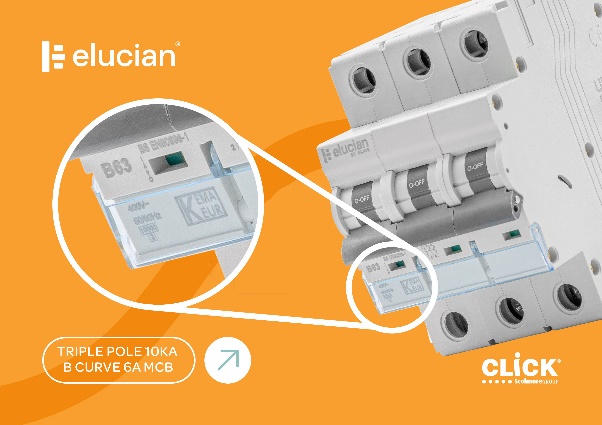
The short-circuit current rating provides the designer/installer with the data necessary to ensure that they select a suitably rated device for the calculated/measured prospective fault current at the point of installation.
Equipment suitable for rated fault current
The level of fault current of an electrical installation is determined by the nature of the supply and Earthing arrangements. The kVA rating of the supply transformer, its percentage impedance, distance from the installation and size of cable are factors in the maximum fault current available.
Regulation 434.5.1 requires that the rated short-circuit breaking capacity of each device shall be not less than the maximum prospective fault current at the point at which the device is installed. Consider Fig 2.
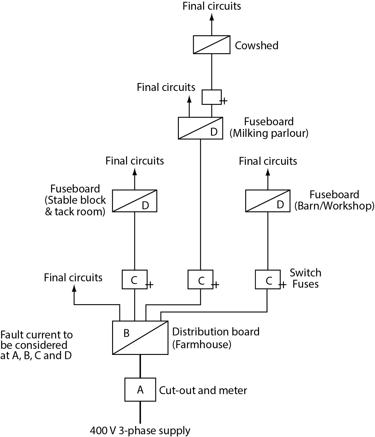
From Fig 2, at position ‘A’ it is normal for the fault current to be at its greatest value. Normally this device is supplied by the DNO and consists of a HRC fuse of some type.
Dependent on the length of cable between Position ‘A’ and Position ‘B’, the prospective fault current will fall by a certain amount. Irrespective of this reduction in fault current, the selection of protective devices should be such that they can withstand the likely fault current.
At subsequent positions ‘C’ and ‘D’ it is likely that the prospective fault current will have fallen significantly due to the length of the sub-distribution cables. It is likely at these positions that the prospective fault current will have fallen to a value below the breaking capacity of the protective devices.
However, the question arises: “What happens if the prospective fault current is greater than the rated short-circuit capacity of the protective device?”
Regulation 434.5.1 recognises this eventuality and permits a lower breaking capacity if another protective device having the necessary rated short-circuit breaking capacity is installed on the supply side.
Therefore, for example, if at Position ‘B’ the prospective fault current is 15 kA (Fig 2) and the protective devices have a rating of 10 kA, there is a clear mismatch. However, if the intake device is a HRC fuse having a breaking capacity of 50 kA, an MCB having a breaking capacity of 10 kA may be installed (lower than the 15 kA) because the HRC fuse has sufficient breaking capacity (434.5.1).
Where this condition exists, a further check must be made to ensure that the characteristics of the devices are coordinated so that the energy let through (I ² t) does not exceed that which can be withstood by the downstream device(s).
More in-depth information on this will be available as part of our ongoing series of Elucian three-phase articles.
Conclusion
When designing electrical installations it is important to assess the prospective fault current and ensure compliance with Regulation 434.5.1 as it relates to the characteristics of fault current protective devices.
Browse the full Elucian circuit protection range here
Find more industry technical articles here