Julian Grant, General Manager at Chauvin Arnoux UK, gives a potted history on the evolution of the clamp meter from its Bakelite clad beginning to the ultra-flexible sensors of today.
In 1937, Chauvin Arnoux invented the Transformer Clamp, which was the first current clamp to utilise the ‘split core hinged jaw’ system that we see in nearly all clamp meters today.

When connected to an appropriate external ammeter, this enabled the AC current flowing in any cable or busbar to be measured quickly and non-intrusively for the first time.
Not surprisingly, the transformer clamp and ammeter were soon combined to produce a stand-alone clamp meter, often referred to back then as a ‘tong tester’, with the current directly readable on an analogue display.

Novelly, to hold a reading on the display a slider on the back of the clamp meter could be pushed, which literally clamped the display needle in whatever position it was pointing. The operator could then remove the clamp, note the reading, and release the needle.
Over the decades clamp meters have evolved to include digital displays, hall effect sensors for DC measurement, and often include a range of typical multimeter functions such as the measurement of voltage and resistance.
More recent developments can also calculate and display other more complex functions such as power, power factor, and harmonics.
Throughout the decades of evolution, they have all continued to use hinged iron core clamps. That was until recently…
Introducing the Rogowski coil
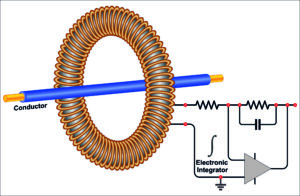
Originally invented in 1912 by German physicist Walter Rogowski, a Rogowski coil consists of a helical coil of wire contained in a flexible sheath. There is no iron core.
Unlike a traditional current transformer, a voltage is induced in the Rogowski coil, which is proportional to the rate of change of current in the conductor that it surrounds. The voltage output from the Rogowski coil is passed through an integrator circuit, which converts it to provide a current output proportional to that in the conductor.

Counter-acting
A derivative of the original coil, sometimes referred to as a counter-wound Rogowski, employs a method where the wire from one end returns through the centre of the coil to the other end such that both connections to the coil are made at one end. Being now both open-ended and flexible, the Rogowski coil can be looped around a live conductor without disconnecting or disturbing it.
Originally somewhat cumbersome devices that could be affected by nearby electrical noise, in more recent years Rogowski coils have reduced in size and increased in performance. Offering much improved immunity to external fields, they are now the current sensor of choice for many test instruments.
Compared to a conventional clamp, they are slim, lightweight and bendable, allowing the sensor to loop around conductors in cramped, hard-to-reach spaces or where multiple cables are closely bundled together.
In contrast, an iron-core clamp meter requires enough space to fit its rigid jaws around the conductor while ensuring they are closed properly. Any gap or misalignment in the jaws would result in potentially significant reading errors.

Broader current ranges
Flexible clamps can often accommodate much larger conductor diameters than conventional clamps and can measure a broader range of current – particularly very high currents – where iron-core clamp meters may saturate or become less accurate. This makes them ideal for measuring currents in large cables or busbars found in industrial and high-power installations.
They are also, however, entirely suitable for looping round much smaller cables, such as those found in domestic and light commercial installations, and in this scenario, could be looped around a cable several times to multiply the current reading and improve the Rogowski coils’ bottom-end measurement capability.
Rogowski coils typically have a higher frequency response than iron-core clamps, making them suitable for measuring transient currents or high-frequency currents such as those caused by harmonics or switching devices. This is particularly important in modern installations that contain increasing numbers of non-linear loads which produce harmonic currents.
Currents with frequencies of up to 5 kHz could be being generated, representing the 100th harmonic in a 50 Hz supply, and this is well within the measurement bandwidth of a Rogowski coil. So many of the conventional clamps in use and available today can only measure currents with frequencies up to 400 or 500 Hz, which will under-report (read low) if higher frequency harmonics are present.
Flexible future
The absence of a heavy iron core makes flexible clamps more portable and easier to carry for field engineers or technicians, and their flexibility further enhances safety in difficult or hazardous environments. Flexible clamps also tend to be more resistant to mechanical damage since they don’t have rigid moving parts, like the jaws in a conventional clamp meter.
In fact, the only real downsides to a flexible clamp when compared to a rigid iron jaw clamp is that they are not great at very low current measurements, bottoming out at about 100 mA. Multiple wraps around the conductor being measured can reduce this, however. Perhaps more crucially, they also can’t measure DC current.
For everything else, perhaps it’s time to ask yourself why you would ever need to use a conventional clamp again.
Get more details on the Chauvin Arnoux range of digital clamp meters here
Find more industry feature articles here


