The experts at NICEIC & ELECSA provide guidance to the contractor when utilising the metallic armouring of a cable as a circuit protective conductor (cpc), main protective bonding conductor or where practicable, an earthing conductor.
Although the main purpose of the metallic armouring is to provide mechanical protection, it may also be used as a protective conductor if all the relevant requirements of BS 7671 for such use are satisfied.
Use as a circuit protective conductor (cpc)
Where the armouring of a cable is used as a cpc it is likely to experience some thermal stress (heating effects) when subjected to earth fault current. The ability to withstand such stress safely will depend upon the cross-sectional area (csa) of the armouring used as a cpc, which must not be less than that determined by one of the two methods referred to in Regulation 543.1.1 of BS 7671, either by calculation or selection.
- Using the formula given in Regulation 543.1.3 based on the adiabatic expression. This provides a more accurate method of determining the minimum csa required for the cpc.

- Using Table 54.7 of BS 7671 for selection, when permitted, and as an alternative to calculation. This will consequently produce a larger required minimum csa. Where the application of Table 54.7 produces a non-standard size it will be necessary to select a conductor with a larger csa.
Selection is dependent on the csa of the line conductor and the associated ‘k’ value for both the line and cpc conductors, providing the minimum csa required for the cpc. However, where the line conductors are sized only by considerations of short-circuit current or where the earth fault current is expected to be less than the short-circuit current the method of selection must not be used (543.1.1).
Where the armouring of the cable is to be used as a cpc, careful consideration must be given to its end-to-end impedance as this will contribute to the earth fault loop impedance (Zs) at the exposed-conductive-parts of all Class I electrical equipment connected to the circuit. As such, the value of Zs at all relevant parts, including the cable armouring, glands and terminations, need to be sufficiently low to satisfy the requirements of BS 7671 for fault protection.
Use as a main protective bonding conductor
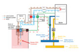
The armouring of a cable may be used as a main protective bonding conductor. With reference to Fig 1, the distribution board is supplied from the main switchgear at the origin of the installation by an armoured cable. In addition, an extraneous-conductive-part is bonded to the main earthing terminal (MET) of the distribution board. The armouring is therefore both the circuit protective conductor for the circuit supplying the distribution board and the main protective bonding conductor between the distribution board and the main switchgear.
 In an installation where Protective Multiple Earthing (PME) conditions apply, also known as a TN-C-S, the main protective bonding conductors may have to carry sustained ‘diverted neutral’ currents in the event of an open PEN (protective and neutral combined) conductor. This may result in the heating of bonding conductors in the installation, including the armouring. For this reason, the armouring of a cable should not be used as a main protective bonding conductor unless it has been determined by the installation designer that under such circumstances, the heat produced in the armouring is not liable to cause overheating of the live conductors or cause damage to conductor insulation.
Where PME conditions apply and the armouring is to be used as a main protective bonding conductor, it must be selected in relation to the PEN conductor of the supply and have a csa of not less than the minimum required by Table 54.8 of Regulation 544.1.1.
Note: Where steel armouring is used for the main protective bonding conductor its csa would typically be required to be 8.0 times that of copper in order to afford an equivalent conductance.
Use as an earthing conductor
The earthing conductor is defined as a protective conductor connecting the main earthing terminal of an installation to an earth electrode or to other means of earthing. Armouring is not commonly used as an earthing conductor based on the sizing practicality issues, although BS 7671 does not preclude such use.
Every earthing conductor is required to have a csa not less than that given by one of the two methods referred to in Regulation 543.1.1. In addition, where PME conditions apply, the csa of the armouring must also be sufficient to meet the requirements for a main protective bonding conductor (Regulation 542.3.1 refers).
Preservation of electrical continuity
It is a requirement of Regulation 543.3.1 that all protective conductors should be provided with suitable protection against:
- Mechanical damage and vibration,
- Chemical deterioration and corrosion, and
- Electrodynamics effects (mechanical forces experienced during fault currents).
In addition to those requirements mentioned above, Regulation 543.2.5 states where the metallic covering including, armouring, is used as a cpc for the associated circuit it must satisfy both requirements (i) (ii) of Regulation 543.2.2, including:
- The need to ensure electrical continuity, either by its construction or suitable connection, and
- The cross-sectional-area shall be at least equal to that resulting from the application of Regulation 543.1 or be verified by test.
Where the armouring is used as a protective conductor suitable cable glands must be used, as shown in Fig 2, for terminating cable ends. Furthermore, electrical joints such as those between the armouring, cable glands and earthing terminals, must be soundly made (mechanically and electrically), and where necessary, suitably protected.

Summary
When using the armouring as a protective conductor its csa must satisfy the minimum size required for the application, using either the method of calculation or selection as Table 54.7.
The continuity of the armouring must be assured for its method of installation while using suitable cable glands and installation methods. Were necessary protection must be provided against the risk of deterioration as a result from mechanical, chemical or electrochemical effects.
Get more NICEIC & ELECSA membership details and support by clicking here