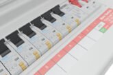
When carrying out new installation works and alterations to an existing commercial premises, it is often found that the circuit identification details on the Switchboard and Distribution Board circuit charts do not provide sufficient details to locate the circuits. The experts at NAPIT offer advice on the correct procedure to follow.
Whenever electrical work is performed, there should never be such little information provided that those following cannot safely proceed with the work.
Electrical safety within any type of premises – either commercial, industrial, or domestic – requires clear and concise information for the safe operation of the electrical installation. Failure to provide this information can result in serious injury, lack of business resilience or unintentional faults.
Too often circuit identification is barely legible, or if it is legible, it is frequently vague. For example, it may read “Office Sockets” or “Lights”. It would be helpful if this information was more detailed such as, “sockets in office area east” or “lights in workshop row 1”
Clear identification of circuits
Within BS 7671 Regulation 514.9.1 it states that a legible diagram, chart, table or equivalent information should be provided along with additional requirements in four bullet points.
The first bullet covers type and composition of each circuit:
● Type of wiring
● Number and size of conductors
● Points of utilisation
With the example in Fig 1, we can see the details have been included for the circuit:
1. 1/Ll the circuit no. and phase designation
2. Details of what and where it is located
3. Wiring type
4. Installation reference method
5. No. of points
6. Conductor size
7. Maximum disconnection time
8. Protective device type and rating
When we are looking at this part it should also include information about the Switchboard or Distribution Board (as shown in Fig 2), such as:
a) Location of the DB
b) The DB identification
c) Details of the number of ways within the DB
d) Number of phases
e) Polarity and phase sequence
f) Source of supply and its location
g) Details of the source protective device
The second bullet covers the requirement from Regulation 410.3.2 for protective measures covering basic protection and an independent fault protection, or a combination of both.
The third bullet covers the identification of each device in relation to the function for protection, isolation and switching, including the location of each of the devices.
The fourth and final bullet is information regarding any circuit or connected equipment that may be vulnerable to, or affect, the electrical tests, as required by Part 6 of BS 7671 on inspection and testing, such SPDs, electronic equipment or USB socket-outlets.
Regulation 514.9.1 also states, for simple installations the information included in the four bullet points can be included in a schedule, normally a circuit chart.
Where larger installations are involved, this normally would include schematic and floor plan drawings and operating and maintenance manuals.
An important part of electrical safety in any property is the clear identification of circuits. This is especially important in premises which are operated by ordinary persons who should be able to identify circuits so that they can take immediate action if they need to, such as turning a circuit-breaker to the off position.
The presence of residual current devices (RCDs) can be recorded on the circuit chart and can give details of the circuits they protect.
Conclusion
On completion of any work within an electrical installation, documentation should be provided to the building owner so they can operate, maintain and have the information to enable periodic inspection and testing to be carried out to ensure the continued safety of the electrical installation.
Get more details about NAPIT scheme registration by clicking here


