Many domestic premises have one or more detached outbuildings such as a garage or home office/studio, which may require an electrical supply from the main installation for lighting and power. This article considers the use of the PME earthing facility in such detached buildings where supplied via a steel wire armoured (SWA) cable.
Concerns are often raised when needing to run a supply to an outbuilding where the main premises utilises a Protective Multiple Earth (PME) earthing facility.
In general, BS 7671 permits the use of a PME earthing facility to such an outbuilding. Where there are no extraneous-conductive-parts present, there is no requirement for main protective bonding to be provided in the outbuilding. However, where there are extraneous-conductive-parts such as metallic services or metallic structural parts, main protective bonding must be provided for these parts (411.3.1.2).
BS 7671 permits the functions of a circuit protective conductor and a protective bonding conductor to be combined in a single conductor where the requirements for both uses are met (542.1.1). The minimum sizing requirements where PME conditions apply are significantly more onerous than where they do not apply, as the sizing is based on the cross-sectional area (csa) of the Protective Earth Neutral (PEN) conductor of the incoming supply (544.1.1).
In such cases, a designer may choose to adopt a TT system earthing arrangement and the installation of earthing electrodes as an alternative option to the PME earthing facility for all or part of an installation. However, this is not without its own issues.
Other than for a number of other special installations, there is no general stipulation within BS 7671 that disallows the exporting of PME earthing to another building.
The risks associated with a PME supply
In a PME earthing arrangement the supply neutral conductor is connected to earth at the source, and at regular intervals along its route via multiple earth electrodes. Therefore, the fault return path for both line-earth and line-neutral faults is via the combined conductor. This method provides a low-impedance return path along the PEN conductor allowing for rapid disconnection of overcurrent protective devices under fault conditions.
In general, PME provides a reliable earthing facility for consumers and, as a result, it should be employed within an installation where provided wherever this is permitted and practicable. However, use of a PME arrangement can pose a risk in certain circumstances.
Example:
Supplies to an outbuilding via steel-wire armoured cable
An outbuilding supplied from the origin in the main building via a 6 mm² two-core steel-wire armoured (SWA) cable having copper conductors and 90°C thermosetting insulation, clipped direct. The cable is protected by a 32 A Type-B circuit-breaker. The conductor size was chosen to address any potential voltage drop issues.
Adequacy of armour to serve as the circuit protective conductor
If the armour of the SWA is to be used as a circuit protective conductor (cpc), its csa should satisfy the requirements for a protective conductor using either the adiabatic equation given in Regulation 543.1.3 or be selected using Table 54.7 of BS 7671.
By calculation
From Fig 3A4 of BS 7671, the current (I) causing disconnection within 0.1 to 5 seconds is 160 A, and the operating time (t) for this distribution circuit is 5 seconds.
From Table 54.4, the factor (k) for steel armouring of a cable employing 70°C thermoplastic insulation1 is 51. So, using the equation given in Regulation 543.1.3:
 1 The calculation is based on the normal operating temperature of the thermosetting insulated conductors not exceeding 70°C and so is based on the current-carrying capacity of the equivalent thermoplastic PVC insulated cable. This is to ensure compatibility between items of equipment and the conductors to which they are connected – see Para 2 of Regulation 512.1.5.
By selection
From Table 54.2, the factor (k1) for line conductors having 70°C insulation is 143.
From Table 54.4, the factor (k2) for steel armouring of a cable employing 70°C thermosetting insulation is 51.
Using the formula from column 3 of Table 54.7:

From Table G2 of BS 5467: 2016 Thermosetting insulated, armoured cables (of rated voltages 600/900 V for fixed installations), the csa of the armouring for two-core 6 mm² cable is 22 mm².
Therefore, the armouring is suitable for use as a cpc whether using calculation or selection.
Adequacy of armour to serve as the main protective bonding conductor where there are no extraneous-conductive parts present
If the outbuilding does not contain any extraneous-conductive-parts, there is no requirement for main protective bonding to be provided (see Fig 1).

Adequacy of armour to serve as the main protective bonding conductor where there are extraneous-conductive-parts present
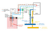
If the outbuilding contains extraneous-conductive-parts such as metallic services (see Fig 2) or metallic structural parts, main protective bonding must be provided for these parts (411.3.1.2).
The sizing of this protective bonding conductor must be based on the PEN conductor of the supply, using Table 54.8 of BS 7671 (544.1.1).

For the purposes of this example, the incoming PEN conductor has a copper csa equivalent to 35 mm².
From Table 54.8 of BS 7671, for a 35 mm² PEN conductor, the copper equivalent csa of the main protective bonding conductor must be not less than 10 mm².
From BS EN 13602: 2013, the resistivity (p) for copper is 17.24 mΩ/m.
From BS EN 10257-1: 2011, the resistivity (p) for steel is 138 mΩ/m.
The csa of the steel wire armouring is calculated using:

As stated earlier, from Table G2 of BS 5467: 2016, the csa of the armouring for two-core 6 mm² cable is 22 mm².
22 < 80.046
As such, it can be seen that the armouring of this cable is not sufficient to act as a main protective bonding conductor.
Referring again to Table G2, for the armouring to be adequate, a two-core cable having 50 mm² circular conductors and armour csa of 86 mm² would be required. This is an unrealistic proposition for the application.
Possible solutions where the armour is of insufficient csa for use as the main protective bonding conductor
The three most likely solutions in this example include:
i) install a three-core 10 mm² SWA cable and use one of the cores as the protective conductor;
ii) install a separate protective conductor having a csa of 10 mm² alongside the SWA; or
iii) choose to not employ the PME earthing facility at the outbuilding and to install electrodes to provide a TT system earthing arrangement.
The first two options become progressively less attractive as the distance between the main premises and the outbuilding increases. The practicality of employing the latter option is dependent on soil/ground conditions in the locality and the risks associated with the driving in of electrodes.
Summary
The PME earthing system is the most commonly used earthing facility within the UK and has the advantage of providing a low resistance earth loop path for fault current, but conversely could cause the touch voltage on connected metalwork to rise to a dangerous level if a break occurs in the supply PEN conductor.
Where the main part of the premises has a PME earthing arrangement, this may also be used for the installation in an outbuilding in most cases. In general, there may be no extraneous-conductive-parts and hence no requirement to carry out protective bonding.
Typically, the distribution circuit to an outbuilding is provided via a steel-wire armoured cable. Where the armouring is to be used as a combined cpc and main protective bonding conductor, it must meet the requirements of both (544.1.1) and (543.1.1) of BS 7671.
As an approximation, a steel conductor should have a csa eight times larger than that of a copper conductor to provide equivalence.
For more information about NICEIC, click here