In the run up to summer, there is one particular subject that will often dominate the Q&A sessions on social media: how to install a hot tub. So, what are the main issues to consider? Pete ‘Monty’ Monfort of Arena Training offers his advice.
Bath or pool?
In the first instance, it makes sense to define what a hot tub actually is. BS 7671 makes no specific reference to hot tubs in either Section 701 (Locations containing a bath or shower) or Section 702 (Swimming pools and other basins).
However, IET Guidance Note 7 (Special Locations) states (at 13.8) that where a hot tub is located in a room such as a garden room, shed, etc., it is recommended that the relevant requirements detailed in Section 701 of BS 7671 should be applied in full.
Where a hot tub is located outdoors in the open-air, the relevant requirements detailed in Section 702 of BS 7671 should be met.
Increased risk of electric shock
The key concerns that electricians need to consider when installing a hot tub relate to the increased risk of electric shock due to:
– minimal or lack of clothing or footwear,
– immersion, or partial immersion, in water, which reduces body resistance,
– availability of earthed metal work,
– increased contact area,
– good contact with the ground where hot tubs are fitted outside.
General considerations
The selection of cables will need to take into account the potential for damage, especially where cables are to be run outside. Designers should consider using steel wire armoured (SWA) cable or suitable cable containment to provide adequate protection. When selecting a suitable protective device, the manufacturer’s instructions should be taken into account.
Occasionally, an installer may even be asked to install a supply, prior to the customer selecting a specific model of hot tub. In this case, the installer should ascertain the maximum power rating for the hot tub, and a good rule of thumb would be to select a protective device with a rated current 25% above the maximum demand, to allow for inrush currents caused by the hot tub motor(s). The selected cable and device must still satisfy Regulation 433.1.1 (Ib < In < Iz).
Installation inside
Where the installation of a hot tub is inside a room, circuits supplying the hot tub and any other equipment in the vicinity of the hot tub (including circuits passing through the area) will need additional protection afforded by one or more RCDs, rated at 30 mA or less (Regulation 701.411.3.3).
In a new installation, all the final circuits are required to meet the requirements for automatic disconnection, be protected by 30 mA RCDs, and have all extraneous-conductive-parts within the location effectively connected to the protective equipotential bonding in accordance with Regulation 411.3.1.2 of BS 7671. In such a case, there would be no requirement for supplementary bonding.
For hot tubs provided with a proprietary three-pin plug, a suitable socket-outlet would need to be provided. This would need to be located 3m away from the boundary of zone 1 (Regulation 701.512.3), which can pose a problem for the installer as some hot tubs may be provided with an insufficient length of flex to reach the socket-outlet.
One solution to overcome this would be to install a socket-outlet in a cupboard or unit, but where this is not practicable the installer might opt to fit a suitable joint and enclosure with a degree of protection of at least IPX4, thereby permitting the extension of the flex. This would permit connection to a fused connection unit or socket-outlet.
Hot tubs with a current rating exceeding 13A are normally hard-wired. Therefore, the installer can fit local isolation by utilising a rotary isolator with a minimum of IPX4 or IPX5 protection at a distance of at least 0.6m from the edge of the hot tub.

Outside installation
Installation outside is similar to that for inside. All circuits would be expected to have RCD protection of 30 mA or less, and a socket-outlet rated at least IPX4 placed outside of zone 1, at a distance of 2m to comply with Regulation 702.53 of BS 7671, would suffice.
However, where this isn’t possible (e.g. a courtyard with a wall), a socket-outlet could be placed a minimum of 1.25m horizontally from the hot tub and at least 0.3m off the floor with a socket comprising a non-conductive cover or cover plate.
Hot tubs requiring a supply exceeding 13A would again make use of a rotary isolator of at least IPX4 or IPX5 rating a minimum of 2m from the edge of the hot tub with a suitable flex supplying the hot tub.
Specific earthing issues
Where a hot tub is to be installed inside a building, the hot tub should be earthed via the cpc in the cable supplying the unit. Where a SWA cable feeding a socket or rotary isolator is utilised, the steel wire armour is an exposed-conductive-part and it must be earthed using a suitable exterior rated gland. It is essential that a gland earth tag arrangement (and earth tail) be utilised to ensure good continuity between the armour and the main earthing terminal (MET) of the supply.
For an outside hot tub, the issue of earthing is more complex and depends on the supply earth.
Where the supply is TN-S, it would simply require the earthing to be supplied via the cpc in the cable supplying the hot tub, as for a hot tub installed inside. However, should the TN-S earthing system be adapted by the Distribution Network Operator (DNO) at a later stage to become a TN-C-S (PME), the designer would need to bear in mind the issues that might arise as described for TN-C-S (PME) below.
Specific concerns relating to TN-C-S (PME) systems
It is advisable to consult the DNO’s guidance relating to the installation of swimming pools (or similar) as they may have specific requirements or indeed, they may not permit connection to the TN-C-S system.
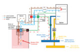
In a TN-C-S system the DNO’s cable utilises a Combined Neutral and Earth (CNE) conductor, otherwise known as a Protective Earth and Neutral (PEN) conductor. When current flows through a conductor a volt drop occurs (V=I.R).
In a PME system, this can give rise to a potential difference between the supply PME earth terminal and true earth. This occurs because load current returns to true earth at the source of the supply through the PEN conductor, which has an impedance. The difference in potential between the MET and the local transformer earthing can vary depending on supply cable lengths and varying loads on the network.
As a consequence, connecting a hot tub (or swimming pool) to the earth terminal of a PME supply can give rise to a small touch voltage between the earth and true earth. Consequently, a person climbing out of the hot tub and placing their foot on the ground may perceive a disconcerting tingle. This isn’t due to a fault with the hot tub and arises for the reason above.
In the majority of cases, hot tubs are designed such that there are no accessible exposed-conductive parts or extraneous-conductive-parts for such a voltage to appear between true earth, but it is worth noting that the water in the hot tub will be in contact with a heater, which will be earthed via the MET and thus a voltage may occur between the water and true earth.
Regulation 702.410.3.4.3 therefore recommends: ‘Where a PME earthing facility is used as the means of earthing for the electrical installation of a swimming pool or other basin, it is recommended that an earth mat or earth electrode of suitably low resistance, e.g. 20 ohms or less, be installed and connected to the supplementary protective equipotential bonding’.
No customer is likely to have given consideration to the installation of an earth mat, and achieving such a low resistance reading with an earth rod may be difficult. However, it may be appropriate to install an earth electrode to supplement the earthing facility provided by the distributor, to prevent dangerous touch voltages, in the event of the loss of the main connection to earth.
An alternative option would be to disregard the earthing of the PME supply and simply earth the hot tub utilising an earth rod and suitable 30 mA RCD protection. If this option was selected, the cpc in the cable supplying the hot tub and the earthed steel armour should be insulated from the earthing arrangements associated with the hot tub. This could be achieved by glanding the cable into a plastic enclosure or using a plastic gland.
Note that the supply cable cpc and steel armour should still be effectively connected to the MET of the supply.
Regardless of the two options, driving an earth rod into the ground, whilst on the face of it, seems straightforward, isn’t without risk. For starters, there is the risk of striking an electrical supply cable, incoming gas or water main, drainage pipe or hard rock. In both cases, Regulation 411.3.1.1 would need to be kept in mind, which states that ‘simultaneously accessible exposed-conductive-parts shall be connected to the same earthing system individually, in groups or collectively’.
In short, this means that you shouldn’t be able to touch any exposed-conductive-parts of another earthing system (including any conductors that be may attached to the main earthing terminal, such as outside taps, pipework etc.) at the same time as any of the hot tub’s earthed parts.
An additional problem associated with the use of an earth rod is the risk of importing a potential as a result of a fault on a nearby PEN conductor (or underground metalwork connected to the MET of a PME supply) that may be carrying a fault current, or worse, be part of a supply that has suffered an open-circuit PEN conductor. The designer will therefore need to ensure that any earth rod is at least 10m from any such underground metal work to minimise this risk (see BS 7430 Code of practice for earthing of electrical installations for further details.)
Ultimately, the designer will need to consider the external environment. Where the hot tub is to be placed on the ground it would be advisable to convert the hot tub to a TT system or utilise the PME system together with an additional rod of suitable resistance, to supplement the distributor’s earth.

What about the danger of open-circuit PEN conductors?
Where an installation forms part of a TN-C-S system, the distributor’s neutral is utilised as the earth, hence the use of the term PEN (Protective Earth and Neutral) or CNE (Combined Neutral and Earth) conductor.
In the event that the PEN conductor is open-circuit due to damage, there is a risk of shock from exposed- conductive-parts and extraneous-conductive-parts connected to the MET of the PME system. Although it is unlikely that a hot tub will have any metalwork present for a voltage to appear to true earth, the designer must bear in mind that a potential could be transmitted to the water through the earthing of the heating element. Adopting a TT system for the hot tub, greatly reduces this risk.
Where an earth rod had been used to supplement the PME supply, this would reduce, but not eliminate, the risk of shock so the designer may therefore wish to take into account whether or not the user of the hot tub could come into contact with true earth, on exiting the hot tub, or preferably some form of insulation, such as raised timber decking, to reduce the risk further.
Summary
To summarise, the installation of a hot tub isn’t straightforward and an experienced electrical installation designer should be consulted to review the installation location, earthing system and manufacturer’s instructions.
Installers and suppliers specialising in hot tubs may wish to invest in and consult (the not inexpensive) BS EN 17125:2018 Domestic spas/whirlpool spas/hot tubs, and BS EN 60335-2-60: Specification for Safety of Household and similar appliances: Particular requirements for whirlpool baths and whirlpool spas.
Looking to the future, the electric vehicle market is driving (no pun intended!) the development of new safety devices, which may have other applications, improving safety even further. It’ll be interesting to see what impact these innovations ultimately have (see BS 7671 Amendment 1, 722.411.4.1).
Visit the Arena Training website by clicking here