Wiring systems must be selected and erected to avoid during installation, use and maintenance, damage to the sheath or insulation of cables and their terminations (522.8.1). Jake Green, Head of Technical Engagement with Scolmore Group, takes a look at suitable means of cable support for a variety of circumstances as well as the requirements of BS 7671.
All cables and conductors must be supported in such a way that the level of mechanical strain which naturally exists will not cause either the cable/conductor or the terminations to be compromised (522.8.5).
Furthermore, all cable supports and enclosures shall not have sharp edges liable to damage the wiring system, and cable/conductors are not to be damaged by the means of fixing (522.8.11 & 522.8.12). It’s important, therefore, that care is taken when selecting for use supports that are appropriate for the cable/conductors.
Types of support
There’s a wide range of options available for the contractor when selecting cable supports. These include, amongst other things:
• Cable ties
• Cable cleats
• Cable clips
• Cable tie accessories
• Cable glands
The type of fixing will depend on the nature of the surface to which the support is fixed. For example, cable ties would be suitable for fixing cables installed on basket tray or cable tray, whereas cable clips would be suitable for wooden surfaces.
Similarly, the type of support will depend on the type of cable being installed. For example, cable cleats will be suitable for steel-wire armoured cables.
Guidance
The guidance issued within the On-Site Guide (OSG) published by the IET is helpful in deciding on the nature of cable support and the distances recommended between clips. Appendix D covers cables generally, specific applications such as caravans and the like, overhead wiring as well as conduit and trunking support.

Table D1 details spacings of supports for cables in accessible positions. Fig 1 gives an example of the recommended distance between clips for a cable having a diameter not exceeding 9 mm, based on Table D1. As the cable diameter increases, the distance between clips is permitted to grow.
Whilst the support distances are important, it remains the case that the purpose of cable supports is to ensure there’s no undue strain on the cable or its terminations.
Similarly, when cables are bent it’s important that there’s no undue strain on the internal conductors caused when the bend is too tight (522.8.3). Fig 2 shows an example of the recommended bending radius for 1.5 mm² insulated and sheathed ‘twin and earth’ (Table D5 OSG).

Cable entry Two issues must be addressed when cables enter an accessory: the risk of damage to the sheath/insulation at the point of entry, and any potential strain on connections.
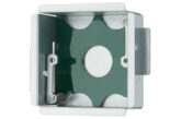
Where a cable enters a metallic accessory box having no protection from sharp edges, there’s a risk that the insulation surrounding conductors may become damaged, leading to arc and shock risk. Where cables enter a metallic accessory box, it’s important that protection is provided, such as with rubber grommets or similar.
Even where cables entering an accessory box or other metallic enclosure are protected from damage, terminations may still be impacted by strain as cables are left unsupported.
In such circumstances it’s necessary for suitable support to be provided and compression glands provided to ensure the electrical and mechanical strength of terminations (522.8.5 and Note).
Conclusion
All cables and conductors must be suitably supported to ensure that no undue strain exists on the cable or the terminations (522.8), so care should be taken to select appropriate support (clips, glands and the like) for cables. Unicrimp has a range of products that can help the contractor in carrying out their duties.
Find more technical articles here

