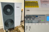
Hager’s Technical Training Manager, Paul Chaffers, discusses RCD Types and applications for electric vehicle charging installations whilst considering the requirements of BS 7671:2018+A3:2024.
RCD terminology
RCD has become a generic term used for many devices that protect against earth faults. With most devices available with different operating characteristics, it is essential that the correct choice is made.
For certain applications, the type and sensitivity may be prescribed, usually by BS 7671:2018+A3:2024 or may be provided as part of a design specification.
RCCB (Residual current operated circuit-breaker without Integral overcurrent protection)
RCCBs are frequently used in split-load consumer units, see Fig 1. They’re designed to make, carry, and break currents by means of mechanical switching and operate when the residual current reaches its set value.

As there’s no integral overcurrent protection provided, a suitably rated overcurrent protective device (OCPD) must be used for the associated final circuit(s). RCCBs are available for single- phase or three-phase applications (2 or 4-pole), usually with 30 mA, 100 mA or 300 mA sensitivity settings, with time delay options for 100 mA and 300 mA RCCBs.
RCCB overload protection
As well as providing overcurrent protection to any final circuits, Regulation 536.4.3.2 requires overload protection to be provided to those devices within a consumer unit that in themselves do not provide this protection. This will usually be the main switch and any RCCBs that are utilised within the enclosure.
Consumer units installed to a previous edition of BS 7671 may well contain 63 A RCCBs. Traditionally, diversity would have been used to assume that these RCCBs will not carry more than their rated current.
However, Regulation 536.4.202 states that overload protection shall not solely be based on the use of diversity. This means that there must be an additional method for providing overload protection.
There are three options which can be used to apply this:
1. Ensure the rated current of the downstream devices does not exceed the rated current of the RCCB or switch. This option, however, could easily be compromised should an additional circuit be added at a later time.
2. Ensure each RCCB and switch is suitably rated for the maximum possible incoming supply (i.e., 100 A). The sum of the individual circuit breakers is no longer important as the maximum current is restricted to 100 A by the supply cut-out fuse.
3. Use individual RCBOs for each circuit and not RCCBs. The rated current of the main switch is still of concern, but if 100 A, would be suitable due to the maximum supply available.
RCBO (Residual current operated circuit-breaker with integral overcurrent protection)
These are designed to make, carry, and break currents by mechanical switching and operate when the residual current reaches its set value. RCBOs can operate independently of any other protective device, and in addition to residual current protection, they provide protection against overloads and/or short-circuits.
RCBOs are commonly available 6 A to 45 A with B or C curve time/current characteristics. See Fig 2 for an example of individual circuit protection.

RCD Types
Regulation 531.3.3 states that different types of RCD exist and advises the appropriate device shall be selected depending on their behaviour in the presence of DC components.
Amendment 2 of the 18th Edition (2022) warned that Type AC RCDs shall only be used to serve fixed equipment where it is known that the load current contains no DC components.
This means that Type AC RCDs are not classified as general purpose anymore; see Fig 3 for RCD Types and operating characteristics.

The issue of impairing (blinding) Type AC RCDs has become well-known in recent years, resulting in the widespread use of Type A RCDs. However, extra measures may be required when there is a known DC presence, for example in electric vehicle charging.
Regulation 722.531.3.101 requires each charging point to be individually protected, meaning it is not possible to use a spare way on a split-load consumer unit to supply electric vehicle charging points (EVCP).
Furthermore, unless a Type B RCD provides protection against DC fault currents, then Type A or F RCDs must be used in conjunction with a residual direct current detecting device (RDC-DD).
RDC-DD devices are often incorporated in Mode 3 charge points and can remove or initiate removal of the supply to electric vehicles in cases where a smooth residual direct current equal to or above 6 mA is detected. The value of 6 mA was chosen to prevent impairing the correct operation of an upstream Type A RCD.
Imagine a Mode 3 charge point with built-in RDC-DD, incorrectly fed from a split load consumer unit Type A RCCB. It’s possible that the charge point could add up to 6 mA of DC through the upstream RCCB in normal operation.
This is not a problem where individually protected, but any extra DC from other final circuits will now exceed what is deemed acceptable and safe for the shared Type A RCCB.
Where split load consumer units have high integrity configuration, it’s possible to individually protect the EVCP, as illustrated in Fig 4.

Thermal considerations
Because EV charging can take many hours with devices constantly loaded, it is important to check with manufacturers what measures are needed regarding applying rated diversity factors when taking into account the mutual thermal influences for the assembly arrangement.
Hager has conducted extensive testing in its ASTA RTL level 4 accredited laboratory (Telford factory) and can verify that a Hager 40 A RCBO or MCB is suitable to supply a 7 kW car charger when in the specific position that’s indicated in Fig 4.
Get more details about Hager’s flexible online CPD accredited learning courses here
Find more industry technical articles here


