Jake Green, Technical Engagement Manager with Scolmore Group, looks at RCDs in general and highlights the necessity of a time delay device when selectivity between RCDs is needed.
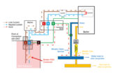
The principle of operation of an RCD is well understood. The live conductors are wrapped around a toroid that is readily magnetised and demagnetised and whilst the current in each live conductor remains the same no magnetic circuit is formed. Should there be an imbalance between the current in the live conductors, usually caused by a current to earth, then a sensing coil ‘picks up’ the newly formed magnetic circuit and a trip is operated (Fig 1).

The typical structure of RCDs of Type AC, Type A and Type F is detailed in Fig 2.

Type AC
The AC type RCD is intended only for those circuits where there are no DC components. This limits their selection to those circuits that are purely resistive.
The impact of constantly applied smooth DC will be to saturate the iron-core of the current transformer within the RCD which will thus become insensitive to any further residual currents. The RCD will, in effect, ‘become blind’ and cease to provide additional protection.
Furthermore, research shows that where a 50 Hz fundamental frequency has an additional, higher frequency component (for example, 500 Hz, 1,000 Hz, or 2.000 Hz), the Type AC RCD may struggle to operate at the rated residual operating current ((IΔn)).
Regulation 531.3.3 of BS 7671: 2018 + Amd 2: 2022 states that ‘RCD Type AC shall only be used to serve fixed equipment, where it is known that load current contains no DC components. Most manufacturers in the UK, including Scolmore, do not produce Type AC RCDs.
Type A
Type A RCDs are to be used for alternating and pulsating DC, possibly including the presence of smooth residual DC up to 6 mA (531.3.3 (ii)). However, as with the Type AC device, once higher frequency components exist then the Type A RCD may struggle to operate at the rated residual operating current (IΔn).

A Type A RCD having (IΔn) not exceeding 30 mA will meet the requirements of Regulation 722.531.3.101 for protection against electric shock by automatic disconnection of supply (ADS) when used in conjunction with a residual current detecting device (RDC-DD) complying with BS IEC 62955 and as recommended by the manufacturer of the charging equipment.
Type B
Type B RCDs are typically voltage-dependent devices (Fig 4).

A Type B RCD has the same tripping characteristics as a Type F device and additionally:
● For residual sinusoidal AC up to 1,000 Hz
● For residual AC superimposed on a smooth DC
● For residual pulsating DC superimposed on a smooth DC
● For residual pulsating rectified DC which results from two or more phases
● For residual smooth DC whether suddenly applied or slowly increased independent of polarity. (531.3.3 (iv))
A Type B RCD having not exceeding 30 mA will meet the requirements of Regulation 722.531.3.101 for protection against electric shock by automatic disconnection of supply (ADS) and does not require to be used in conjunction with a residual current detecting device (RDC-DD).

The table above details the RCD types and their associated symbols along with their properties and relevant standard.
Time delay RCDs
A time-delay RCD (typically, S Type) is specially designed to attain a predetermined value of limiting non-actuating time1, corresponding to a given value of residual current (BS EN 61008-1; BS EN 61009-1).
An S Type RCD operates more slowly than a non-time delay device and minimises the risk of unwanted operation. However, this benefit means that as such an RCD is not permitted to be used as a means of additional protection.
S Type devices are necessary where it is required for selectivity to be achieved between RCDs.

Where selectivity is required, Regulation 536.4.1.4 states that selectivity occurs under the following conditions:
● The upstream RCD is of a selective type (Type S typically), and
● The ratio of the rated residual operating current of the upstream RCD to that of the downstream RCD is at least 3:1.
The practical working out of this means that a 30 mA device would require a minimum of a 100 mA Type S RCD upstream to provide selectivity.
As part of the Elucian range, Click Scolmore has produced a series of time delay (S Type) RCDs (63 A, 80 A and 100 A) which provide the necessary selectivity for suitably rated downstream devices.

Conclusion
Great care should be taken by the designer and installer to ensure the correct type of RCD is selected and erected for a specific application. An S Type device is essential when selectivity is required.
When in doubt, contact the manufacturer.
Key references
1The non-actuating time is the maximum delay during which a value of residual current higher than the residual non-operating current can be applied to the RCCB without causing it to operate (BS EN 61008; BS EN 61009).
To browse a copy of the latest Elucian catalogue click here