NAPIT’s Bill Allan and Donald Holmes offer expert advice on the correct methods for supporting cables above suspended ceilings.
It has long been accepted as good practice to support cables above suspended ceilings. The two main reasons for this are electrical safety and fire safety. However, you may have seen cables slung over suspended ceilings in a haphazard fashion and resting on the ceiling grid.
Various reasons are given for this practice, such as:
- Running the cables in the shortest distance between two points is the quickest and cheapest solution.
- If you have to return to that site to carry out an addition or alteration, life is made more difficult if the cables are supported.
- There are so many cables already resting on the ceiling that it seems pointless to support the cable(s) we install.
- The client is unwilling to pay for the extra expense of supporting the cables.
None of the above reasons are valid, and here’s why:
- Regulation 522.8.4 of BS 7671 requires that conductors or cables are to be supported by suitable means at appropriate intervals in such a manner that the conductors or cables do not suffer damage by their own weight. When cables rest on the inverted ‘T’ section of a ceiling grid, the edges of which may well be sharp, they are liable to suffer damage by their own weight.
- Regulation 522.8.5 states that every cable or conductor shall be supported in such a way that it is not exposed to undue mechanical strain.
- Section 522.6 concerns the protection of cables against impact, which includes minimising damage caused by abrasion and penetration.
- Cables laid on top of ceiling tiles prevent easy access to the ceiling space.
- There is a potential fire hazard when cables are laid over light fittings.
- Under fire or flood conditions, the suspended ceiling could be brought down and unsupported cables would be brought down with it, leading to the consequent risk of entanglement.
- Suspended ceilings are not designed to take the additional weight of cables.
- Refurbishments sometimes remove suspended ceilings to open up the area and this should be possible to achieve without the need for a rewire.
Methods of supporting cables
Makeshift solutions
Anecdotal evidence indicates that electricians sometimes fix cables run above suspended ceilings by a number of unorthodox and improvised means. NAPIT is not opposed to the use of improvised solutions provided they can be shown to contribute to the safety of the installation and meet the requirements of BS 7671.
Recommended solutions
Stretching catenary wires across the ceiling space is one of the cheapest options due to the speed of installation.
Installing catenary wires
A catenary wire rope is usually made from galvanised steel wire which can be PVC-coated, or it can be made from stainless steel wire. Typical sizes for a catenary wire rope are 2mm, 4mm and 6mm diameter.
A typical 4mm wire rope pack will contain the following components, as illustrated in Fig 1: 10m of 4mm wire rope, two thimbles, six wire rope grips, one turnbuckle and two wall plates.
Having decided where you’re going to fix the wall plates, drill four holes in the brick or stone work in line with the holes in the wall plate. Insert suitable fixing plugs or bolts into the holes. Secure one of the wall plates to the wall, ensuring the staple is horizontal and using the appropriate size of screws or tightening the bolts (if bolts are used). Repeat the process for the other wall plate.
Place the hook of the turnbuckle onto the staple of the wall plate (Fig 2a). Moving to the other wall plate now, fit the wire rope by marking off where the three grips and thimble will go. Starting at the ‘dead’ end of the wire rope mark the position of the first grip, then a further 25mm in for the second grip and 25mm again for the third grip, ensuring there is at least six times cable diameter gaps left between the grips. Then mark at least 120mm and this should be the top of the thimble, once secure.
Put the thimble on the staple of the wall plate by opening the thimble with a pair of pliers, put through the staple and close it back up, as illustrated in Fig 2b. Loosen off of the three grips and push the wire rope through all three grips. Push the wire rope through the staple of the wall plate, bottom up, and then back through the grips to make a loop.
Ensure the U-bolt is on the dead side of the wire rope and, starting at the ‘dead’ end, tighten the first grip on the first mark, then the second grip on the second mark. Put the wire rope round the thimble then tighten the third grip to secure the thimble, ensuring it does not touch the grip. Then re-torque the nuts until they are all tight and pressing into the wire rope, as illustrated in Fig 2c.
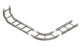
Now unwind the wire rope before marking off the length required. To do this, mark the wire rope at the eye of the turnbuckle, then add 120mm and cut the wire rope using cable cutters or an axel grinder to ensure a clean cut. Repeat the same procedure as for the first wire rope end. To achieve the desired wire rope tension, tighten the turnbuckle (Fig 2d). Cables can then be attached to the catenary wire by means of metal clips and hangers, making sure that the cables are adequately supported throughout their length. Alternatively, metal cable tray could be used with metal cable clips fixed to the tray. Metal trunking is also another solution.
Conclusion
NAPIT takes the view that wiring systems in all areas of buildings – not just in escape routes – must be supported to ensure that they will not be liable to premature collapse in the event of a fire. All cables above suspended ceilings are not exempt from this rule. As a NAPIT Registered Installer, you can access a wealth of technical information, guidance and advice.
If you would like more information on joining a NAPIT scheme, visit:
www.napit.org.uk call 0345 543 0330


