Julian Grant, Managing Director of Chauvin Arnoux, looks at why proper earth resistance testing takes the guesswork out of installing earth electrodes.
Never have earth electrodes been more relied upon than they are now in the latest Amendment 2 of BS 7671. In addition to their main use in TT systems, they’re now recommended in TN systems as an additional earth connection (Reg. 411.4.2).
Many special locations such as swimming pools, generating sets, EV charging points and even cow sheds may rely on a good connection with the general mass of earth via a suitable earth electrode for their safety. So, modern electrical contractors are increasingly likely to be designing, installing and testing earth electrode systems.
When constructing a new installation or when carrying out additions or alterations to an existing installation, it is now essential that the same consideration is given to the design of the earthing system as would be given to the design of the final circuits. Proper design of the earthing system will ensure a safe, quick and cost-effective installation.
Once the requirement for earthing is established, it is necessary to choose a suitable means of earthing and its location. Using an earth resistance tester, like the Chauvin Arnoux C.A 6472, you can perform a simple soil resistivity test. This test is often overlooked by those installing earth electrodes, but can clearly show the best place to install your earth electrode.

Two methods of testing resistivity
There are two standard methods of resistivity testing – the Wenner and Schlumberger methods. Both methods allow you to map resistivity for a single location at varying depths or across a whole survey grid.
Soil resistivity data can also be used to aid your choice of electrode type. By siting your electrode based on resistivity survey data, you remove the costly trial and error that can experienced when siting by guesswork alone.
You should consider performing soil resistivity testing as early as possible in the planning and design process. This critical information can affect key decisions, such as the location of services or even the location of buildings themselves. In many cases the choice of locations for an earth electrode may be limited or even predefined by others, so some quick resistivity testing can hopefully confirm the suitability of the chosen location in advance and any potential problems can be addressed early.
Where a new earth electrode has been installed, and as part of our initial verification of the installation, we are required by BS 7671 to measure the resistance to earth (Reg. 643.7.2). There are many ways to perform earth resistance testing and this largely depends on the type of installation being tested.
In the case of initial verification of a newly installed earth electrode, it could be argued that performing a ‘live’ external earth fault loop impedance test, which is currently common practice by many electricians, poses a safety risk by applying mains voltage to an, as yet, unproven earth path.
Also, the electricity at work regulations limit such ‘live’ working to situations where it is ‘unreasonable’ for it to be ‘dead’. The IET follow this logic with their note on regulation 643.7.2 stating that a measurement of external earth fault loop impedance may only be used if an earth resistance measurement is ‘not practicable’.
Standard earth resistance testing – a better option?
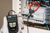
So, we can see that while a loop impedance test can be used in specific circumstances, a better and safer option for initial verification would be to perform a standard earth resistance test using a suitable 3-pole or 4-pole tester such as the Chauvin Arnoux C.A 6424 or C.A 6460. Many modern MFTs (like the Chauvin Arnoux C.A 6117) also have the facility to perform these tests.
Earth electrode resistance testing is carried out using the Fall of Potential (FoP) method. In addition to the electrode under test (E), two shorter test electrodes – the current electrode (H) and the potential electrode (S) – are inserted into the ground. The current electrode (H) should be sufficiently far away from the electrode under test (E) to avoid overlap of their individual ‘zones of influence’ – this distance varies for each installation but 30m would be a typical example.
The potential electrode (S) is placed at a point 62% of the distance between the initial two electrodes and a measurement is then taken. To confirm there is sufficient separation between E and H, S is moved 10% in each direction, i.e. 52% and 72%.
Two further readings are taken. If the three readings are similar, then the average of the three readings can be taken to be the measured earth electrode resistance RA.
However, if there is a significant variation in the three readings, there may not be sufficient separation between E and H for the test to be valid and it should be repeated with H located further from E.
This process may seem complex at first, but in real life it takes very little time to perform and is simple to achieve in a majority of locations.
For more complex installations with multiple electrodes, earth resistance clamps, like the Chauvin Arnoux C.A 6417, offer an alternative to the FoP method with no need for additional test electrodes.

In summary
Following the launch of Amendment 2, it is inevitable that consumer earth electrodes will be used more widely in UK installations. It is therefore important that all electricians have the ability to perform the necessary tests to work safely and cut out the costly guesswork.
To get more technical advice and support from Chauvin Arnoux, click here