Julian Grant, General Manager of Chauvin Arnoux UK, recounts how loop tests have evolved over the last 40 years and explains the inherent measurement variability that has occurred along the way.
Most technical support questions received by manufacturers of test and measuring instruments generally concern issues related to Earth Loop Impedance test results. More specifically, the variations in readings obtained with successive measurements, comparisons between different test instruments, or readings that are an issue, such as just outside of the permitted minimum value for a particular installation.
Why is loop testing important?
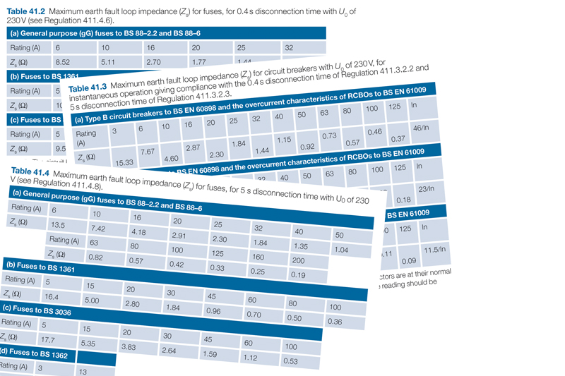
For a protective device in an electrical installation to operate within the maximum permitted time detailed on Table 41.1 of BS 7671, the earth fault loop impedance (Zs) for the circuit must not exceed the maximum earth fault loop impedance values for the protective device given in Tables 41.2 to 41.4.
The earth fault loop path typically consists of the external impedance (Ze) and the resistance of the phase and protective conductors (R1 + R2). If the total impedance of the fault path is too high the fault current will be insufficient to meet the required disconnection time for operation of the protective device.
Zs can be obtained by adding the result of external earth fault loop impedance (Ze) test to the measured value of (R1 + R2) obtained at the furthest point of the circuit, or by taking a direct measurement of (Zs) at that point using an earth fault loop impedance test instrument.
But if the loop tester is required to measure a value that is near the bottom of its range, such as on an installation with TN-C-S earthing system and a Ze of 0.35 Ω, the accuracy of the test instrument can have a significant effect on the displayed value. This is an issue which has been made worse over the years as loop testers have had to deal with testing on RCD or RCBO protected circuits without tripping them, and on installations with more electrical noise and harmonic currents than ever before.
Back in the day
35 years ago, a loop tester would basically perform a high current test by applying a 10 Ω load to the supply being tested and then measure the voltage drop across it.
It could then calculate the resistance of the loop and display it. These tests were generally performed for two half-cycles of the mains supply, and with a test current of around 23 A, loop testers were able to produce fairly accurate results.
Since then, installation equipment and products have evolved, and loop testers today are very different instruments.
Instead of high test-currents, the introduction of RCDs and a desire to keep products small, lightweight and able to perform large numbers of tests without going into thermal overload, pushed manufacturers to utilise test currents below 15 mA and/or test durations that are so fast the RCD does not have time to react.
Even the high current loop tests in most products today only operate at a few amps, rather than the 23 A used in the past, due to the need to reduce circuit size, costs and heat dissipation. This was something that became even more necessary with the need to fit the loop testing circuit into a multifunction tester as the popularity of MFTs increased.
Using smaller test currents makes it much more difficult to obtain reliable measurements and increases the susceptibility of those measurements to the effects of electrical noise and harmonics, all of which reduces the accuracy of the results.
This required manufactures to develop ever more sophisticated measurement techniques, resulting in different test methodologies from different manufacturers, leading to slightly different measurement results.
The level of potential variability in a loop test is published in the specifications of the test instrument’s user guide, however, such things often go unread and unfortunately for many there is a natural inclination to take what is on the display as the definitive test result.
Specifications and their effects
Some typical loop test specifications and the variability of result they can give on a 0.35 Ω loop are shown in the table (below). The products are not identified, but they are all popular brand MFTs currently available in the UK and these figures are taken directly from the manufacturer’s published specifications.

Apart from the accuracy % of reading, the number of digits represents variability of the least significant digit on the display.
Accordingly, ±5 digits on a 0.01 Ω resolution range means the reading can be out by an additional ±0.05 Ω. And a loop with an impedance of 0.35 Ω, measured on a product with 0.01 Ω resolution and an accuracy of ±5% ±5 digits, could be displayed anywhere between 0.28 Ω and 0.42 Ω which equates to ±20%.
Similarly, a 0.10 Ω loop impedance measured on the same product could be displayed as 0.05 Ω or 0.15 Ω, an error of ±50%.
Avoid all doubt
To avoid any doubt, always try to use an instrument where the expected loop test values for the installation under test are well within the range and limits of the instrument.
Some MFTs available today, including the Chauvin Arnoux CA6117, incorporate a 0.001 Ω resolution loop test range which would be a benefit.

If your product measurement accuracy is inadequate for the job in hand, other methods of assessing the circuit’s characteristics might be more appropriate, such as using a calculated or enquired value for Ze.
Awareness of the precise measurement capability of your equipment, and the need to understand if the variability in readings mean the loop test range is suitable or not for the job in hand, are essential to ensure accurate results. If you don’t know already, look in the specifications section of the user guide or contact the manufacturer.
Get more technical support and advice from Chauvin Arnoux here
Find more industry technical articles here