This article from the experts at NICEIC discusses the purpose of carrying out protective equipotential bonding in commercial and/or industrial type properties, and how to verify the electrical continuity of protective bonding conductors in such a location.
Introduction
The majority of electrical installations typically use Automatic Disconnection of Supply (ADS) as the protective measure for protection against electric shock.
In this article, the requirements of BS 7671 for protective equipotential bonding where ADS is used are considered. ADS is a protective measure in which:
- basic protection is provided by basic insulation of live parts or by barriers or enclosures, in accordance with Section 416; and
- fault protection is provided by protective earthing, protective equipotential bonding and ADS in the event of a fault, in accordance with regulation Groups 411.3 to 411.6 (411.1 refers).
Where it is not feasible for an overcurrent protective device (OCPD) to provide the necessary disconnection time in accordance with regulation 411.3.2, or the use of an RCD for such purpose is not appropriate, reference should be made to Section 419 (411.3.2.5).
Purpose of main protective bonding
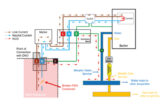
In the event of an earth fault (a fault between a line conductor and an exposed-conductive-part or a protective conductor), a dangerous voltage – or more correctly, potential difference – can occur between simultaneously accessible exposed-conductive-parts and extraneous-conductive-parts in the installation, as shown in Fig 1.
The primary purpose of main protective bonding is to limit the magnitude of any potentially hazardous touch voltages that may appear on exposed and/or extraneous-conductive metalwork within an equipotential zone with exposed-conductive-parts.
Requirements for protective bonding
In each consumer’s installation within a building, main protective bonding conductors complying with Chapter 54 of BS 7671 are required to connect any extraneous-conductive-parts, which are liable to introduce a dangerous potential difference, to the MET in accordance with regulation 411.3.1.2.
Extraneous-conductive-parts may be considered as conductive parts which do not form part of the electrical installation but may inherently introduce a potential, generally Earth potential. Regulation 411.3.1.2 lists examples of items that can be extraneous-conductive-parts.
The note to 411.3.1.2 states that where non-metallic services, such as polyethylene gas or water pipes, enter a building and are then connected to metallic pipes within the building, as they are unlikely to be extraneous-conductive parts there is no requirement to provide protective equipotential bonding.
Regulation 411.3.1.2 also requires that the connection of a lightning protection system to the main bonding shall be in accordance with BS EN 62305 – Protection against lightning. The regulation further states that main bonding conductors shall be connected to the metallic sheath of any communications cable at the premises, provided that the consent of the owner or operator of the cable has been obtained. Where consent is not granted, such details should be recorded on the appropriate electrical certification.
Commercial or industrial installations
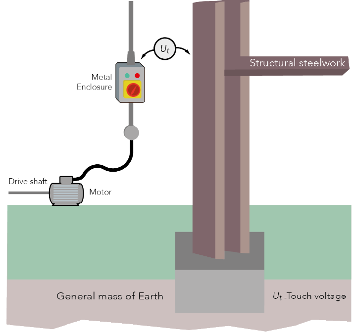
As mentioned previously, it is a requirement for all extraneous-conductive-parts such as exposed structural steelwork, to be connected to the MET. However, what designers and installers may not appreciate is that, in many cases, the structural steelwork can be utilised as a protective bonding conductor, as shown in Fig 2 (543.2.1 (vii)).

Where the steel structural framework of a building is to be used as a protective conductor, regulation 543.2.6 requires the following conditions to be met:
(i) its electrical continuity can be assured for the life of the installation;
(ii) the cross-sectional area (csa) of the steelwork is not less than the minimum csa given by the application of regulation 543.1.1 whether:
- calculated in accordance with regulation 543.1.3; or
- selected in accordance with regulation 543.1.4;
(iii) unless compensatory measures are provided, precautions shall be taken against its removal; and
(iv) it has been considered for such a use and, if necessary, suitably adapted.
Using the steelwork as a protective bonding conductor provides many benefits, not least that less cable is needed, particularly in larger installations, and that the steelwork provides a more convenient and efficient method of maintaining continuity as the steelwork is unlikely be removed.
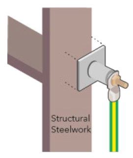
The connection from the accessory to the steelwork must be electrically and mechanically secure for the duration of the installation (526.1). Where a bonding connection is to be made, it is necessary to obtain prior permission before drilling holes arbitrarily. An alternative method is to have a connection plate (as shown in Fig 3) welded to the structure. Other methods of making a secure connection are not precluded.
Verification of electrical continuity
As with all protective bonding conductors, unless it is clearly visible throughout its full length and it can be assured the connections are electrically and mechanically secure, it will be necessary to perform continuity testing (643.2.1(i)). Such testing ensures that all protective bonding conductors, where fitted, are not only continuous but provide a sufficiently low ohmic value.
Any extraneous-conductive-part without an effective connection to Earth will not provide an equipotential zone with any simultaneously accessible exposed-conductive-parts, which may lead to a risk of electric shock in the event of an earth fault. The test method typically used is the long lead (wandering lead) method, as shown in Fig 4.

Before using a long lead, it should be remembered to null the test leads or make a note of their resistance before carrying out the test.
Having temporarily disconnected the main protective bonding conductor from the MET, the leads of the instrument should be attached, as shown in Fig 4. Note that where structural steelwork is used, it will be difficult to isolate any potential parallel paths.
Where significant differences are observed in the resistance readings between simultaneously accessible extraneous-conductive-parts and exposed-conductive-parts, it may be necessary to install supplementary bonding – for example, as shown previously in Fig 1, between the metal cased motor starter and the structural steelwork.
Note: It should be remembered to reconnect the main protective bonding conductor to the MET after completing the test.
Summary
The primary purpose of main protective bonding is to minimise the magnitude of any touch voltages.
Where the building structure consists of substantial steelwork, regulation 543.2.1 (vii) permits its use as a protective bonding conductor.
As part of the verification process for ensuring continuity of any protective bonding conductor, there is no difference in the testing procedure where the structural steelwork has been used in preference to the use of individual copper cables.
Get more details about NICEIC membership and benefits here