Paul Chaffers, Technical Events Manager and Technical Author of NAPIT’s On-site Solutions guide, takes a closer look at the potential issues associated with using TNC- S supplies for outbuildings.
A question that is often raised by contractors is: ‘can I use a TN-C-S (PME) earthing system to supply an outbuilding?’
Unfortunately, the answer is not always black and white, and like a lot of areas of electrical installation design, it requires engineering judgement to be applied.
This article is a small extract from NAPIT’s On-site Solutions guide, which contains many installation examples and explores the various possibilities whilst providing useful solutions to everyday electrical installation tasks.
 Protective Multiple Earthing (PME) Restrictions
When supplying an outbuilding from a TN-C-S (PME) supply, we need to be aware of what issues can occur. BS 7671 prohibits the use of PME for some locations; caravan parks and marinas have special requirements, for example. This is because the Electricity Safety, Quality and Continuity Regulations (ESQCR) prohibit the connection of a PME earthing facility to any metalwork in a leisure accommodation vehicle. Further conditions regarding PME apply to most Part 7 sections within BS 7671 for special installations or locations. But why?
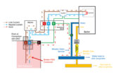
PME is a TN-C-S system, where the neutral and earth functions are combined in one conductor (the PEN conductor) on the supply side of the installation. The PEN conductor is referenced to Earth in multiple positions with Earth electrodes, as illustrated in Fig 1. For overhead supply cables, this is carried out at the transformers and several utility poles between the transformer and installation. Underground cables are generally earthed along the length of run with electrodes.
Historically PME systems have had the advantage of being backed up by numerous fortuitous connections to Earth via metallic pipes, etc. that are connected to the network via nearby installations’ protective bonding, consequently providing a form of supplementary earthing. This accidental connection should never be relied upon, however it does play a considerable part in PME earthing systems. Whilst the neutral and Earth is then separated within the installation, the PME characteristics can cause issues when using PME outside of an installation; one issue is known as a perceived shock.
Perceived shock
Fig 1 shows the main building is supplied via a TN-C distribution system, with the nearest Earth electrode somewhere outside in the street. This distance could be considerable, perhaps 30 or 40 m away. A perceived shock can arise from touching anything metallic connected to the PME system of the main building, such as an item of Class I equipment, whilst being in contact with true Earth. For outbuildings, such as our example, there can be a potential difference between the true Earth and the Earth exported from the main building. This is due to a voltage drop in the PEN conductor, caused by the returning load current, and is something that happens under normal operating conditions.
The problem is made worse when the body resistance is low. For example, imagine having a garden party in the summer; all the kids are jumping in and out of the pool, saturating the grass, and you have set up a temporary beer fridge at the bottom of the garden, fed from the outbuilding. Anyone in contact with the fridge whilst standing bare foot on the wet grass, stands a good chance of feeling an unpleasant tingle from the potential difference.
This is because any stray earth leakage from the fridge is taking the path of least resistance, and in this case, it’s through the wet body back to a nearby earthed position, which is not necessarily the installation’s earth, just one on the system, see Fig 1.
PEN Conductor – Open Circuit
More of a concern than perceived shocks are hazards associated with the loss of neutral on the supply. This can happen due to a breakdown of an underground cable joint or possibly the neutral becoming disconnected on an overhead supply, for example, on a utility pole by a falling tree. The problem is, if the line conductor remains connected, the returning load current will not be able to return to source due to the loss of neutral, and because both the neutral and Earth are connected at the service head, the load current will now seek alternative return.
Consequently, all exposedconductive- parts and extraneousconductive- parts connected to the PME installation will rise in potential, creating an electric shock risk. Protective equipotential bonding will limit the effects inside the equipotential zone. However, outside is a different story and could be fatal.

TT system for outbuildings
As can be seen from the aforementioned concerns, many electricians will be forced to make an engineering judgement on the likelihood of a potential problem based on all the factors presented to them on the job. If the PME supply was being used for a light fitting in a wooden shed where all fittings were plastic and the shed had a wooden floor, the likelihood of a problem would be small.
On the other hand, if the shed had socket-outlets that could be used for equipment outside, then a possible issue could arise. It should be noted that accidents relating to the loss of a PEN conductor are few and far between. In fact, the same shock hazard will apply to any PME installation where the supply neutral has been lost and there is a metal outside tap that is connected to the earthing arrangement by means of protective bonding.
For any outside installations where there is concern with using the PME supply from the main building, it is recommended that the outbuilding is made into a TT system. This involves the use of a local Earth electrode instead of using the Earth from the main building. The PME earthing should be disconnected at the outbuilding posi tion. This can be achieved by using an insulated adaptable box, or by means of an insulating gland to separate earthing systems.
Fig 2 shows an example of a detached workshop with TT earthing arrangement. This allows the overcurrent protective device in the main building to operate if a line to Earth fault should occur on the supply cable. A local RCD provides fault protection for the circuits within the workshop.
It is worth labelling the inside of the adaptable box to ensure this intentional separation of earthing systems is not reconnected in the future by a less experienced electrician – see Fig 3 for an example label.
Conclusion
Hopefully this article has demonstrated that there is not always a definitive answer for such design choices and contractors should be mindful of this when carrying out EICR work, as some outbuildings may use PME with little risk attached.
Where in doubt use a TT earthing system to avoid any potential issues.
Get more details on NAPIT scheme registration by clicking here