Chauvin-Arnoux UK’s Julian Grant discusses the implications of voltage imbalance on the electrical supply of an installation, why it could be of critical importance, and how to avoid it.
A three-phase power system is said to be balanced when the phase voltages have the same amplitude and are separated by a phase angle of 120˚. Accordingly, voltage imbalance describes a variation in a power system in which the voltage magnitudes, or the phase angle differences between them, or both, are not equal.
Voltage imbalances are caused by big single-phase loads, such as induction furnaces, traction systems, and other large inductive machines, either drawing a current between one phase and neutral that does not appear on the other two phases, or between two phases such that current is only drawn on two out of the three. Either way this causes the higher loaded phases to experience a greater voltage drop, reducing the voltage on those phases for all the other equipment connected to the same supply.
The uneven distribution of lower power, more general, single-phase loads across a 3-phase system can also sometimes be bad enough to cause a slight voltage imbalance. This often occurs over time as an installation, originally balanced during its construction, has additional circuits and equipment added to it.


Getting the balance right
In rarer cases, voltage imbalance can be caused by the unequal degradation or failure of one or more PFC capacitor units in a bank, and temporary voltage imbalances can be produced by a fault on any one of the phases either within the facility or further back up the supply network.
Having balanced phase voltages is arguably one of the most important requirements for an industrial installation, particularly if it contains 3-phase motors. Unbalanced voltages at motor terminals can cause a phase current imbalance of up to 10 times the percentage voltage imbalance for a fully loaded motor. Accordingly, motors operating on imbalanced supplies need to be de-rated with significant reductions in available loading for relatively minor voltage imbalances. Imbalances can also require the necessary de-rating of power cables due to increased I2R losses in the cable.
According to the IEC, voltage unbalance is defined as the ratio of negative sequence voltage to the positive sequence voltage. Basically, the 3-phase voltages can be mathematically expressed as a sum of positive, negative and zero sequence components. Positive sequence voltage creates flux in the direction that the motor is intended to rotate, and negative sequence voltages rotate in the opposite direction. This creates flux in the opposite direction, however, since the positive sequence voltages are always much larger when the direction of motor rotation is not affected.

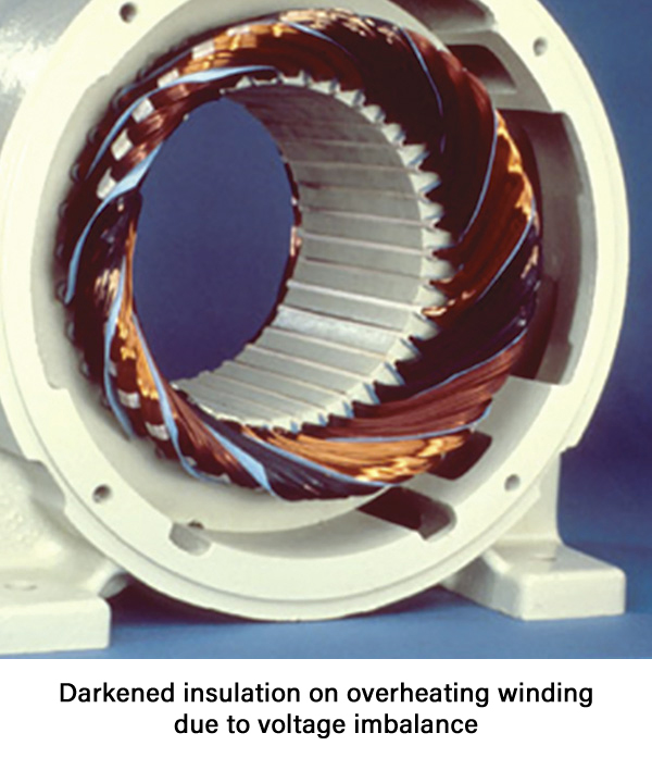
The counter rotating negative sequence flux caused by negative sequence voltages creates additional heating in the motor windings that will eventually lead to insulation breakdown and premature motor failure. A continuous operation at 10°C above the normal recommended operating temperature can reduce rotating machine life by a factor of two.
IEC 60034-1 imposes a 1% negative phase sequence voltage limit on the supply feeding machines. However, EN 50160 states that imbalances of up to 3% can be expected. Apart from the motors themselves, many solid-state motor controllers and inverters include components that are especially sensitive to voltage imbalances. Some will protect themselves and the motor in the event of voltage imbalance and refuse to operate. For less sophisticated devices reduced life of Variable Frequency Drive (VFD) front end diodes and bus capacitors are a common result of voltage imbalance.
UPS, polyphase converters, and inverter supplies also perform with reduced efficiency in the face of voltage imbalances on the supply, creating unwanted ripple on their DC side and, in many cases, also creating increased harmonic currents on the supply.
The case for energy logging
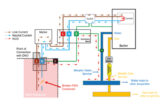
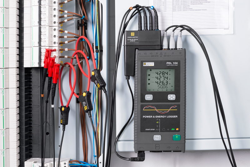
Fortunately, the measurement of voltage and load (current) balance, and therefore the identification of imbalance, is easily achieved using a power and energy logger (PEL). Connected at the incoming supply, the loading across the phases for the whole installation can be monitored over time to see how it might vary during the normal operating day or week.
PELs can be quickly moved around the installation, non-intrusively connected, and utilised to measure individual equipment or circuit loads and voltages to achieve balance throughout the installation, and then reconnected to the incoming supply for ongoing monitoring. As well as voltage and load balance this will enable measurement and monitoring of other power quality parameters including power factor and harmonics.
There are two obvious precautions or actions to reduce voltage imbalance and its effects. Firstly, use separate circuits for large single-phase loads and connect them as close to the point of the incoming supply as possible. This will ensure that the load does not cause a voltage drop on any wiring utilised by other equipment that would then be subjected to that voltage drop. Secondly, ensure that all single-phase loads, large and small, are balanced evenly across all three phases. These two simple steps could save a lot of headaches and expense.
Find out more about Chauvin Arnoux here