The technical experts at NAPIT examine the differences between Earthing and Bonding.
What’s in a name? These two principles are often confused, either by name or purpose. Let’s be clear, they both have vital roles to play in an electrical installation, but they’re both very different in the way they achieve their requirements.
The only real similarity they have is the green and yellow cable we use to denote them, which is where the confusion between the roles they fulfil is likely to stem from.
Earthing conductors
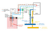
Earth, or the greater mass of Earth, is where we consider the fault path for current to flow to in the event of a fault.
That flow is channelled via earthing conductors. Where the supply is a transformer, the earth point is usually the star point or neutral of the windings. As earthing conductors carry fault current, they have to be designed to withstand enough current to initiate the operation of an overcurrent protective device (OCPD) within the times stated in BS 7671, Table 41.1.
Depending on the OCPD, the required fault current can be many times the magnitude of a device’s normal operating current.
So, when we look at the circuit earthing conductor, or circuit protective conductor (cpc) as we refer to them, for a final circuit in a TN-C-S system, protected by a 32 A B curve MCB, it needs to be capable of handling 160 A for 0.4 seconds.
In reality, a B curve MCB will operate almost instantaneously at 160 A.
We can see from this requirement that we have to size our cpc or earthing conductor with the current flow they’re expected to see in the event of a fault. There are a couple of ways we can do this: use Table 54.7 in BS 7671 or calculate the size we need.
In order to calculate the size we need, we use the adiabatic equation given in Regulation 543.1.3 and shown in Fig 1.

Earthing conductor re-cap
So, to put that all together, earthing conductors used for cpcs must meet the following criteria:
- They need to carry large currents for a short duration
- They can be sized in accordance with Table 54.7 in BS 7671 or
- They can be sized using the adiabatic equation in Regulation 543.1.3.
Using the adiabatic equation allows the use of smaller cross-sectional diameters of conductors than complying with Table 54.7. By doing this, the designer can use smaller, more cost-effective cable sizes.
Inspectors need to be aware of this when carrying out EICRs as an undersized cpc may have been calculated using the adiabatic equation and therefore will be more than adequate.
Protective bonding conductors
Bonding conductors, or more accurately, protective bonding conductors, can be either:
- Main protective bonding conductors or
- Supplementary bonding conductors.
They’re both similar in their principles, but as the name suggests, one is very much larger than the other.
Main protective bonding conductors
Main protective bonding conductors are used to connect extraneous metallic parts to the main earth terminal (MET). We use the word ‘bonding’ because we’re bonding or connecting two parts together to create a zone of equal potential, or an equipotential zone – as it is known.
Where extraneous metallic services or parts enter a building and are in contact with the general mass of Earth, it is possible that they can introduce a voltage which can be different from that of the installation’s MET or, indeed, other extraneous metallic parts.
When this happens, there is a potential for current to flow, dependent on the voltage magnitude and resistance of any conductor – we call this a potential difference. If the potential difference has enough magnitude, it can cause a fatal electric shock.
By bonding any extraneous metallic parts and the MET together, all of the different services and parts are at the same potential difference, and current cannot flow between them. Main protective bonding conductors are sized in two ways depending on the earthing system being used.
All installations, except protective multiple earthing (PME), are sized in relation to the installation’s main earthing conductor (MEC), where the main protective bonding conductors must be not less than half of the cross-sectional area of the MEC and no less than 6 mm2.
Conductors sized in this way need not exceed 25 mm2 copper or its equivalent. For PME earthing systems, the main protective bonding conductors must be sized in accordance with BS 7671 Table 54.8.
This Table gives varying sizes a bonding conductor can be, based on the cross-sectional area of the incoming supply’s protective earthed neutral (PEN) conductor, but they can be no less than 10 mm2 and need not be bigger than 50 mm2 copper or its equivalent.

Main protective bonding conductor re-cap
Quite different to earthing conductors, bonding conductors meet the following criteria:
- They’re not designed or required to carry large currents; they only balance the potential difference between extraneous parts,
- For PME installations, they must be sized in accordance with Table 54.8 in BS 7671,
- For non-PME installations, they can be no less than half the cross sectional area (csa) of the MEC and no less than 6 mm2.
Main protective bonding conductors cannot be calculated using an adiabatic equation; they must be sized in accordance with Regulation 544.1.1 or Table 54.8.
Supplementary bonding conductors
These carry out a similar role to main protective bonding but at a smaller scale, usually on an individual circuit, in an area that may benefit from a more localised equipotential zone.
Areas currently requiring supplementary protective bonding are Part 7 special installations or locations:
- 701: Locations containing a bath or shower (this is usually relaxed where indents iv, v and vi of 701.415.2 have been met),
- 702: Swimming pools and other basins,
- 705: Agricultural and horticultural premises,
- 706: Conducting locations with restricted movement,
- 710: Medical locations,
- 740: Temporary electrical installations for structures, amusement devices and booths at fairgrounds, amusement parks and circuses.
Supplementary bonding conductors are generally much smaller in csa than main protective bonding conductors but must be no less than 2.5 mm2 for mechanically protected conductors and 4 mm2 for non-mechanically protected conductors.

Conclusion
Earthing and bonding are two very different principles – one relies on carrying a high current to clear a fault, and the other relies on equalising any potential difference of voltage, so it isn’t likely to carry much current at all.
For more information on NAPIT scheme registration, click here