This article from the experts at NICEIC focuses on Section 710 of BS 7671 concerning electrical installations in medical locations, and aims to consider the requirements for the use of medical IT systems within a Group 2 location.
To mitigate the increased risk to patients in a Group 2 medical location, the total loss of power due to a fault or a failure of supply should be prevented (710.512.1.2).
Where such risk of loss of supply is considered greater than the risk associated with the existence of a fault, then an isolating transformer to BS EN 61558-2-15 is to be used providing galvanic separation. This transformer in conjunction with the medical grade insulation monitoring device (MED-IMD) and other components such as insulation fault monitors and temperature alarms form the medical (IT) system configuration.
In general installations, IT systems using isolation transformers are typically recognised as one of the means of providing protection against electric shock with live parts isolated from Earth, or while connected to Earth through a suitably high impedance (411.6.1).
However, due to the increased risk to patients, the medical IT system is not primarily used to provide protection against electric shock.
Medical IT systems
The principal purpose of the medical IT system in a Group 2 location is to improve the resilience of the final circuit supplying socket-outlets. This effectively provides protection against first (earth) fault, allowing a single earth fault to exist on a final circuit while maintaining the leakage current within an acceptable limit.
During this period the insulation monitor will activate while the fault location equipment (where installed) will identify which final circuit is experiencing a low insulation fault.
At this point, while the fault remains, which could be on L1 or L2 (L2 being the conductor usually connected to the ‘N’ on the BS 1363 socket-outlet) the socket-outlets from that medical IT system are effectively TN socket-outlets without RCD protection. In the event of a second fault to earth occurring on the other ‘leg’ of the transformer to earth for any other connected circuit, the overcurrent protective device(s) must meet the requirements for automatic disconnection of the supply (ADS).
Unless the second fault occurs on the same circuit, where a second fault occurs it is likely that two final circuits are affected. Therefore, appropriate action must be taken by the users of the systems when the alarms are sounded.
Fig 1 shows a typical medical IT system arrangement in which there is no direct connection between live parts and Earth. However, the exposed-conductive-parts of the installation are earthed.

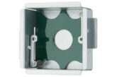
Medical IT systems may be housed in a floor-standing cabinet (see Fig 2) incorporating the distribution board to BS EN 61439 series with overcurrent protective devices for final circuits within the location, ancillary devices for communication and/or monitoring, and the isolation transformer in accordance with BS EN 61558-2-15.

In many cases, it may also be necessary to incorporate ventilation and cooling to prevent excessive temperatures affecting operation of installed equipment.
Manufacturers of such systems often produce equipment having a current rating of 4 – 10 kVA (18 A – 44 A) which may incorporate single-phase 230 V 50 Hz isolation transformers, or where required, multiple transformers.
Where a medical IT system is to be used in a Group 2 location, it should comply with the requirements of 710.411.6.3.1, 710.411.6.3.2 and 710.512.1.1. These relate to alarms and indicators with the latter regulation relating to the position of the medical IT system with respect to the medical location it serves.
Regulation 710.411.6 identifies that medical IT systems are to be used to supply ME equipment and ME systems, although it should be recognised that not all equipment is compatible for use on medical IT systems.
Items of equipment that should not be connected to the medical IT system are identified below. It should be noted that the list is not exhaustive.
- Supplies to provide movement of fixed operating tables.
- X-ray equipment.
- Large equipment with a rated power greater than 5 kVA.
Where a group of rooms are used to provide the same patient treatment, regulation 710.411.6.3.1 requires at least one medical IT system be provided.
In addition, at least one single-phase transformer shall be provided for the supply of the medical IT system per room, or for functional groups of rooms. The rated output of each transformer shall not be less than 0.5 kVA and shall not exceed 10 kVA (710.512.1.1 (ii)).
A typical example may include a pair of neighbouring operating theatres. For resilience of supply, each theatre may have a separate medical IT system while sharing an equal number of distributed circuits between the two locations. Where the medical IT system is required to supply a three-phase load, a separate three-phase transformer shall be provided (710.512.1.1 (iii)).
The medical IT transformer should be located on the same floor level and be contained within the same fire compartment as the medical location they supply. However, the note to regulation 710.512.1.1 implies that where it may not be practical or difficult to locate the medical IT system within the same fire compartment, additional measures may be provided to achieve equivalent compliance.
Similarly, regulation 710.511.1 requires that any associated distribution board supplying circuits in a Group 2 medical location shall be installed on the same floor level, immediately adjacent to or, where permitted, in locations that they supply. In such case, clear labelling shall be provided.
The intention of these regulations, in addition to that of equipment manufacturer’s instructions, is for the medical IT distribution systems to be installed as close as possible to the clinical process they serve, and, in particular, provide a constant means of accessibility to such equipment in case of a system fault.
When selecting a suitable location for the installation of the medical IT system, preventative measures must be applied to mitigate the thermal impact, and any excessive heat produced by the transformer(s) during normal use.
Although the windings of a medical IT transformer are typically designed to operate in excess of 100°C prior to activating an alarm during an overload condition, the heat produced during normal use may influence the operating characteristics of overcurrent protective devices, typically those mounted at high level within the IT cabinet.
Similarly, excessive heat may create a risk of damage to neighbouring batteries used for the uninterruptable power supply (UPS) systems. Adequate ventilation or suitable means of cooling should therefore be provided in accordance with manufacturer’s instructions to minimise the thermal impact on such equipment.
Leakage current
Regulation 710.411.6 of BS 7671 places a limit on the total leakage current for medical IT systems which should not exceed 10 mA.
This limit takes account of the maximum permitted leakage current of 0.5 mA for the IT transformer output winding to earth and the leakage current of the enclosure when supplied at a rated voltage and frequency.
This maximum value also includes the total leakage current of all final circuits connected to the medical IT distribution system under no-load, and while taking account the cables capacitance (710.411.6 and 710.512.1.1 refers). The purpose of this is to limit the length of run of medical IT system final circuits by making the designer consider the capacitive leakage current of the final circuits.
Installation designers should therefore refer to cable manufacturers’ data when determining the total leakage current based on the cable’s capacitance.
Likewise, note 5 to regulation 710.411.6 recommends that the length of final circuits connected to the IT distribution board does not exceed 25 m.
Each medical IT system supplying a group of rooms while providing the same function, shall be equipped with an MED-IMD, as shown in Fig 1, complying with both Annex A and Annex B of BS EN 61557-8.
Such a monitoring device shall be capable of alerting clinical staff within the medical location, or more specifically, where ME equipment is being used, by providing an audible and visual alarm with the first fault, or generally, when there is a reduction in the insulation resistance to a minimum of 50 kΩ.
Similarly, the IT transformer should also be provided with a means for monitoring overload and any increase in temperature (710.411.6.3.2). In addition to the insulation monitoring device, each medical IT system serving more than one room or more than one patient place of treatment, shall be provided with an insulation fault location system complying with BS EN 61557-9 (710.411.6.3.3).
Many systems incorporate a user graphical interface, which is often linked with other controls and building management systems (BMS), enabling access and control of multiple functions from a single point within the Group 2 environment such as lighting, ventilation, and humidity, as shown in Fig 3.


Fig 3. User interface panel with circuit fault identification capability
The user interface enables the operational state of all IT circuits within the medical location to be clearly and easily recognised. For example, during a circuit fault, an audible alarm will sound, and consequently the screen icon relating to the particular circuit will change colour depending on its fault condition, as indicated in indents (i) to (iv) of 710.411.6.3.1 (see Fig 3).
Detailed text notifications may also be displayed to help identify the precise location of the fault. The interface should therefore be installed in a suitable position where ME equipment is being used so that it may be permanently monitored by clinical staff.
Supplementary alarms associated with the Group 2 environment may also be required at a close but remote location, often positioned at the nursing base for example.
It should be noted that as nursing techniques change, the location of an alarm at the nurse’s base is not always appropriate as the use of local touchdown facilities enable the nurses to be with patients. Therefore, such methods of working should be considered when determining where the alarm should sound.
Summary
Although IT systems are typically recognised as a means to provide protection against electric shock, this article in particular has focused on the requirements of Section 710 and the medical IT system used as a means to provide a resilient source of supply in a Group 2 medical location, or where ME equipment is typically used.
We would like to acknowledge and thank Brandon Medical for providing the images used within this article.
Get more details about NICEIC registration here
Find more industry technical articles here