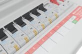
Richard Townsend, Principal Technical Author at NAPIT, looks at the problems facing designers who may be specifying heavy current using equipment connected to consumer units.
Calculate or determine? That’s the question
Calculating the maximum demand of an installation’s capacity using diversity, along with taking account of equipment ratings, has always been a dark art. There are numerous ways to calculate them; although the only real way is to use a data logger to determine what happens. This is not ideal for the designer who is working with a clean sheet, and the installation currently doesn’t exist.
As an industry, we’ve always used diversity factors, the most favoured being about 80 years old, so not ideal for today’s modern energy efficiency-driven industry. It is, however, a starting point.
So, what is diversity?
Diversity is a factor that we allow in some installation designs, which takes account of the full design load of a circuit not being used all of the time, the sockets on a circuit not being loaded to maximum, or indeed some circuits hardly being used at all, such as a bell transformer for a doorbell.
We refer to this holistic approach to determine how much load the installation will actually draw in reality as ‘diversity’.
It allows for a much more accurate actual maximum demand than simply adding all of the possible different circuit load currents together, which could well be two to three times larger than the DNO supply cut-out, so not ideal and far from reality.
Calculate or determine maximum demand using diversity
The maximum demand of an installation is often difficult to determine; there is no single answer or way to achieve this. The On-site Solutions publication recommends taking the largest rated circuit and adding 40% of the total of the remaining circuits to give a maximum demand figure.
However, this is entirely subjective and can be fine-tuned if the designer knows the likely load characteristics of the installation.
Typical installations measured with a data logger, not incorporating EV chargers, can see very low load signatures, often below 25 A, which helps immensely when looking at using diversity to calculate or determine maximum demand.
Assembly rating
On top of the maximum demand, we need to look at the rated current of the consumer unit and its assemblies. This rated current has the symbol (InA).
InA the rated current of an assembly (consumer unit) is not necessarily the rating shown on the incoming device and is required to be provided on the consumer unit designation label. It’s important to understand that when we add supplies to an installation, such as generators and solar systems, these extra incoming supplies need to be taken into account and incorporated into the rated current of the CU.
In is the rated current or current setting of the incoming circuit overcurrent protective device, either incorporated within the low voltage switchgear and control gear assembly or upstream of it, and Ig(s) is the rated output current of the generating set or sets; then the rated current of the assembly InA must be equal to, or in excess of, the combined values of In and Ig(s), seen here in the following formula:
Formula: InA ≥ In + Ig(s)
We can see this requirement more clearly in Fig 1.
The total required rating for the CU InA needs to be 116 A. In reality, this is likely to be 125 A as this would be the next rating size above 100 A.
Rated diversity factor (RDF)
After all of that, we need to look at how we arrange those loads within the CU.
When manufacturers give ratings to assemblies, they take into account how much load could be placed on them and how the thermal effects of those loads could alter how those incorporated devices react.
Where the devices in a consumer unit run at their design loads continually, which isn’t often, manufacturers de-rate the devices by as much as 50% for a 10-way board and above, as can be seen in Table 1.
This is done because when a device such as an MCB or RCBO runs at its design current, it will start to warm up; if the device next to it in the CU is also loaded to its maximum, the combined heat of the devices will start to affect each other internally.
Without adequate cooling, the bi-metal strips, which form part of the overload current protection within the devices, will start to operate. These bi-metal strips operate on the build-up of heat, usually from the device running in excess of its load current, but when that heat is added to by a device placed directly next to it, the strip can operate prematurely, as the extra heat causes it to operate as if there was a high current being drawn.
This means that with a diversity factor of 0.5, a 32 A MCB/RCBO could only be rated to 16 amps if the devices surrounding it are heavily loaded and its ability to cool adequately is hindered. This isn’t new and has been around for a while now; manufacturers put the rated diversity factor (RDF) in place to combat future perceived high continual loads, such as electric vehicle (EV) charge points.
The advice from NAPIT and manufacturers is to spread out high loads in a CU and put spaces or blanks between devices that operate at, or close to, their circuit design currents.
Where less used or lower load circuits are available, such as lighting, alarms, or external lighting, place these between, or next to, higher loaded circuits.
Doing this will help mitigate the thermal effects of heat transfer between devices and help higher-loaded devices to cool down naturally by being away from high loads. Although we don’t typically see these issues very often, as more EV charge points and other high loads are installed, we could start to see protective devices operating in an unwanted manner.
Conclusion
As both designers and installers, we must resist the temptation to install devices in a CU in a uniform manner. We often install the larger ones altogether, followed by the next capacity down and so on; installers need to take account of the possible RDF de-rating of a CU and mix circuits to aid cooling and high load separation.
Add to this the input from a solar array or other generators, plus any further complications from a heat pump and/or electric heating, and we can see how complex our domestic installations will become in the very near future.
For more information on NAPIT scheme registration, click here


