In this regular column, ‘Dr Zzeus’ Tom Brookes, MD of Zzeus Training and chairman of the FSA, answers your questions related to fire safety compliance.
In the previous column (December 2023), I answered a question related to the skills of fire alarm and security installers and whether some of the old skills have been lost.
This gave advice on how to measure the resistance of a cable and also how to calculare the resistance of a 1.5 mm standard fire alarm cable.
This month we’re going to answer a final question that relates to the subject: how do you take an insulation reading on a fire cable?
As stated previously, BS 5839-1 clause 38.1 states that all installed cables with a manufacturer’s voltage rating suitable for mains use should be subject to insulation testing at 500 V DC Insulation resistance should be measured between each conductor and earth and achieve no less than 2 MΩ.
It continues to say that on completion of the installation work, where maximum circuit resistance for any circuit is specified by the manufacturer or supplier, measurement of the resistance of every such circuit must be documented.
At Zzeus Training, this is standard day three practical electrical testing, but it may appear that some training providers are not doing this. The standard is very clear: if you install a fire cable, you must test it.

Insulation resistance testing
Resistance is a measure of how difficult it is for current to flow and is measured in units called ohms (Ω).
The insulation resistance test definition is the measurement of total resistance between any two points separated by electrical insulation. This measurement identifies if, down the length of the tested cable, the insulation between the cores is in good condition. The higher the reading, the better the insulation is.
The standard allows 2 MΩ as a minimum reading; however, on brand new soft skin fire cable, I would expect to see a reading greater than the meter can calculate. The new cable with a 2 MΩ reading has got a serious problem. This test needs to be done with no devices on the circuit because it will put 500 V DC through the cable, which may damage equipment or indeed shock a person.

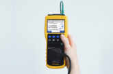
Testing for insulation resistance is very simple with a multifunction tester:
Step 1
Attach the live lead to your first core and attach the earth lead to the second core.
Step 2
Select ‘Insulation Testing’ on the meter and ensure the test voltage is set at 500 V DC.
Step 3
Press the test button, keeping your fingers away from the test leads and cable.
The results will measure the resistance in megohms (millions of ohms). Remember, the higher the number, the better the insulation!
Do you have a question you’d like answered? Email your queries to: Tom@Zzeus.org.uk
Get more details about Zzeus Training and the range of courses on offer here