The experts at Megger offer guidance to ensure the safe testing of EV charging points.
The demand for electric and hybrid vehicles has been rising steadily over the last few years and now, with government policy being implemented to ban the sale of pure internal combustion engine vehicles by 2030, this rise will continue exponentially.
As a result, the need for a comprehensive charging infrastructure is paramount, with charging points already found in public car parks, company premises and many domestic properties. But is charging the vehicle batteries at these locations always safe?
As with any new electrical installation, the EV charging point circuit is required to be tested in accordance with the latest version of BS7671, to minimise the risk to individuals and their vehicles by ensuring the installation is safe. This brings in to question how a contractor can fully test the protective devices within the charge point itself.
Mode 2 or 3?
It is worth noting that EV charge points with a dedicated circuit that are used solely for the purpose of recharging electric vehicles, are described as Mode 3 Charge Points. Mode 2 uses a socket-outlet, with the cable between the socket-outlet and the vehicle incorporating an “In-Cable Control and Protective Device” (IC-CPD).
Mode 3 charging stations and charging points can operate with either a single phase 230 V or 3-phase 400 V AC supply. They can generate very high currents to allow vehicle batteries to be charged in as short a time as possible. This continuous load can, however, cause faults or overloads in the electrical systems if not designed and installed correctly. This can lead to potentially dangerous situations.
For this reason, all charging points must be equipped with suitable protective devices which, in the event of a fault materialising, operate to remove the potential of electric shock, damage to a vehicle (or it’s batteries) or fire.
Therefore, periodic inspection and testing should be carried out on the charge point, as with any other electrical circuit, in accordance with the latest amendment of BS7671. Guidance on initial verification and periodic inspection and testing is given in the IET Guidance Note3: Inspecting and Testing and, upon completion of the required tests, either an Electrical Installation Test Report or an Electrical Installation Condition Report should be issued.
Be aware that special locations often require compliance with other regulations, for example, inspection, testing and maintenance requirements for filling station installations should comply with APEA/EI publication: Design, construction, modification, maintenance and decommissioning of filling stations.
Who can test?
Any work carried out on an electrical installation must be performed by a suitably qualified electrician and/or competent person. The definition of this can be found in the latest version of BS7671. There are now specific Level 3 City & Guilds course designed to cover EV charging equipment installation in domestic, commercial and industrial and street applications, 2919-01 and 2919-02, that covers both the theory and practical aspects of installation and verification.
On completion of an installation or inspection, and before being put into service, the installation must be inspected and tested to verify that it complies to BS7671 as well as any charging equipment manufacturer’s specific instructions.
On completion, an Electrical Installation Certificate, together with any schedules of inspection and test or an Electrical Installation Condition Report shall be given to the client/owner. Megger CertSuite provides several specific EV Test Certificates that can be incorporated into these reports.
How is testing of a Mode 3 EV charge point carried out?
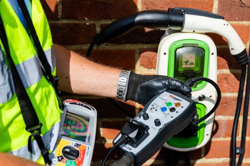
The following sequence of electrical and functional tests are detailed using the Megger EVCA210, along with the MFT1741+ Multifunction Tester:
On completion of the installation of the charge point and the relevant fixed installation tests of the supply circuit, a number of additional tests are undertaken.
The required functional tests are:
- PE Pre-test (confirming no potential on the earth to vehicle)
- PE Error (safely creates an earth fault or missing earth on vehicle)
- CP Error (safely creates a fault on AC side of the charging circuit)
- Mechanical interlocking of the connector
- Further tests as required or as recommended by the charging point manufacturer.
The required electrical tests are:
- Earth loop impedance
- Testing of the protective devices (RCD and RDC-DD)
- Phase sequence (for 3-phase systems).
With the supply circuit turned on and the EVCA210 plugged in to the charge point, a PE Pre-Test must be carried out. This test is completed prior to any other testing to confirm no dangerous potential is present on the earth.
If a potential is indicated, further testing must cease, and the cause must be investigated and rectified as a potential high voltage may be present on the earth, giving rise to the risk of an electric shock to the operator or other persons nearby.
The PE Pre-test is easily completed using any EV adapter designed in accordance with the IEC/EN61851-1 and IEC/HD60364-7-722 standards.
Following the PE Pre-Test, two further functional tests are completed to ensure the charge point operates correctly in the event of a fault conditions.
Both tests require the charge point to be in a charge-required state. This is achieved by two rotary switches on the front of the EVCA210 that define both the proximity of a vehicle (vehicle connected) and the rate of charge required.
Details of the various adaptor settings can be found within the EVCA210 manual. At this point it should also be confirmed that the interlock (if fitted) should prevent the connector from being removed.
Functional tests
The first functional test is the PE Error. This safely simulates a PE conductor disconnection that, when pressed to initiate, should cause the EVCA to stop the charge process immediately and disconnect the charging circuit. Once released, the charge point should automatically reset and commence the charging process again.
The second is the CP Error. CP (Control Pilot) is the means by which a vehicle connected to the charge point communicates the level of charge current required. When pressed, the CP Error button should again cause an immediate disconnection of the charge point current and stop the charging process. As before, when released, the charge point should automatically reset and a new charging session start.
Following completion of the functional test, the electrical tests as defined above are then completed using relevant electrical test equipment. The Megger MFT1741+ model allows the user to complete all the tests required.
In the event of a 3-phase charge point being tested, a phase rotation test should be completed to verify the phases have all been terminated correctly. Then a simple earth loop impedance value should be measured using a proprietary no-trip test to ensure the protective device in the charge point or distribution board does not disconnect.
Next, a complete RCD test must be undertaken. In addition, however, all new charge points installed today have an additional 6 mA DC monitor – or in some cases an RDC-DD – that ensures that no DC can be fed back into the utility supply. This test is a simple DC ramp that should measure the leakage current and ensure that a trip occurs within the 6mA threshold and the allowed 10 seconds time.
Finally, if no vehicle is available, a simple load test can be carried out – to ensure that charge point is delivering the correct charge current – through the EVCA210. This is limited to 10A for a short duration. Mode 2 charging cable Even if a mode 2 charging cable is included with the electric vehicle, this shouldn’t be used as a permanent charging solution.
These mobile charging cables are intended for charging at standard 13A (BS1363) or industrial (BS EN 60309-2) sockets, when no permanently installed charging device is available. For regular operation, charging at a charging station or permanently installed charge point is recommended.
The combination of the EVCA210 and MFT1741+ will still allow the safe functional and electrical testing of a Mode 2 charging cable with a IC-CPD installed.

To watch a demo video of the Megger MFT1741+ and EVCA210 in action, click here