In the second of this two-part series, Paul Chaffers, Technical Events Manager and Technical Author of NAPIT On-site Solutions, takes a closer look at some of the important design considerations for cable ladder and tray systems.
In the previous article that ran in last month’s edition of Professional Electrician, I introduced the requirements for cable ladder systems and cable tray systems. As discussed, the differences between the wiring containment of cable ladder and tray systems and other forms such as conduit and trunking systems is that they are not enclosures. They are in use for the support of cables, which already have the additional insulating sheath or forms of mechanical protection.
As highlighted in the first article, the requirements of Regulation 521.10.1 would be breached if non-sheathed conductors were installed in cable ladder or tray systems as these cables have to be contained in an enclosure. Consequently, only cables where mechanical protection is provided by a suitable sheath, for example, PVC sheathing, MICC, fire resistant cables to BS 7629-1 or steel wire armouring, can be used in conjunction with ladder and tray systems.
Site modifications
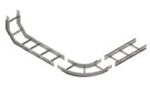
Many contractors will be familiar with the joys of fabricating tray work on-site. Fortunately, most components these days are factory-made and widely available, such as the example in Fig 1, showing a curved divide to segregate the cables installed on the cable ladder. However, where modifications are made on-site, including simple operations such as cutting and drilling, any bare or sharp edges must be dealt with to avoid abrasion to the cables or injury to those involved in installing the cable and it must be sealed appropriately to prevent corrosion. Manufacturers will be able to advise which products should be used. For example, repairing the galvanized finish on a section of the tray must be carried out in accordance with BS EN ISO 1461. This type of repair is generally carried out using zinc-enriched touch-up paint.
Protection against corrosion can be addressed by using alternative materials, such as zinc aluminium alloy components rather than using traditional hot dip galvanisation. Fig 2 shows an example of a steel wire cable tray/basket arrangement with a range of accessories available for site alterations to allow for installation in all manner of building types. The steel of the cable tray can be cut and shaped to route the cables as required. The example demonstrates the use of purpose-built accessories to connect the cable tray into the desired configuration. Note the reference to hand protection as the edges of the cable tray can have a sharp edge after cutting.
Protective earthing and bonding
A question that is often asked is: does a cable ladder or tray system need to be earthed or bonded? Unfortunately, there is not a straightforward ‘yes’ or ‘no’ answer to this one. Every installation is different, so this question needs to be further broken down into the following questions:
Is the ladder or tray system being used as a protective conductor?
Regulation 543.2.1(vi) permits metallic cable management systems to be used as protective conductors. Designers are unlikely to select or use a ladder or tray for a protective conductor, and therefore, it would not require earthing, but depending on the environment, risk of damage to cables, and fault current levels, designers may decide to connect it to earth.
Is the ladder or tray system deemed to be an exposed-conductive-part?
As previously mentioned in this article, cables generally need to be Class II construction (insulated and sheathed), or they may be Class I bare copper MICC. In any case, earthing is not required because the sheath is providing fault protection.
Is the ladder or tray system deemed to be an extraneous-conductive-part?
It is unlikely that a ladder or tray system would introduce a different potential into a building and, therefore, not require protective bonding. However, where containment traverses multiple buildings, equipotential zones, or is in contact with the general mass of Earth externally to the installation, it could be deemed to be an extraneous-conductive-part. In these cases, protective bonding may be required in accordance with Regulation 411.3.1.2.
Electrical continuity
Where electrical continuity is required, manufacturers will be able to advise on which systems are classified as having electrical continuity in accordance with BS EN 61537:2007, which is the international standard specifying requirements and tests for cable ladder and cable tray systems. Common practice will be to fit additional copper earth straps in accordance with the manufacturer’s instructions. For clarification, see Fig 3, showing an example from the Legrand Swifts cable tray range of accessories.
Conclusion
Hopefully, this series of articles has highlighted a few areas of design and installation that require care and attention to get right. Considering the sheer weight and complexity of cable ladder and tray systems, it is recommended to consult directly with manufacturers’ technical guides to obtain the required information to complete a safe and satisfactory installation.
*NAPIT would like to thank Legrand for the source material used in this article.
For more information on NAPIT Scheme Registration, click here


