This article from the experts at NICEIC discusses intelligent cable Bus technology, such as the KNX system, for the connection and control of smart devices within a building, and as an alternative to using wireless devices.
This article considers the function(s) of a communication Bus system, such as KNX, and its ability to permit interconnected control of devices using twisted multi-pair cable (KNX TP).
KNX is a control system based on a common standard for commercial and domestic building services automation that allows products from various manufacturers to work seamlessly together. Communication between devices is achieved using the dedicated KNX protocol, guaranteeing interoperability between the many manufacturers signed up with the KNX Association.
The KNX standard allows communication through other types of media, offering a higher degree of flexibility in system design, however, only KNX TP will be considered in this article.
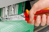
Cables used with KNX systems are similar in construction to that of Ethernet cables, typically incorporating a foil screen protecting the twisted pairs1 from interference.
The conductors are terminated into dedicated connectors allowing for termination into any KNX device, as shown in Fig 1.

The use of cable Bus systems is more often associated with larger installations such as commercial and industrial type premises. However, such use is becoming increasingly popular when designing new installations for larger domestic premises.
As shown in Fig 2, local lighting and shutter radial circuits can be connected directly into their output channels of the associated actuators which incorporate switching and dimming functionality, therefore negating the need for a conventional type localised wall switch2.

Although actuators often have many channel outputs facilitating control of multiple circuits, consideration should be given for the provision of separate lighting circuits within larger installations over multiple actuators.
Some devices offer means to measure current, switching cycles and power consumption within a circuit. Additionally, a back-up function is often provided with manual on/off switching in case of communication failure on the Bus.
Generally, some form of training in the installation and application of the chosen equipment will be necessary.
The KNX system
The wired KNX system operates on a series of British Standards, BS EN 50090 and International Standards, BS ISO/IEC 14543-3. Each KNX device has the ability to function independently, thereby removing the need for a centralised control system. Because KNX is an open protocol3, communication between devices on the cable Bus is possible using around 6,500 products from 400 assigned manufacturers on any particular system.
Many of the devices are typically DIN rail mounted in an enclosure often located adjacent to the consumer unit. Although, flush type devices are also available, and commonly used in metal back boxes and ceiling voids within existing installations.
All input/output devices, including wall switches, sensors and actuators are interlinked to the KNX network Bus via a dedicated cable.
Cabling
Regulation 557.6.2 of BS 7671 recognises the need to take into consideration the characteristics of a cable when used in auxiliary circuits for the control of relays (actuators). The rated voltage of an auxiliary circuit, and the components used, shall be compatible with the supply to that circuit. Excessive voltage drop in an auxiliary circuit may reduce the reliability of operation of the actuators and other components within the system (Regulation 557.3.5.1).
In-line with the KNX standard, manufacturers of such control systems often specify a dedicated type of cable and a maximum length, to ensure signal quality and system reliability against issues such as voltage drop and, consequently, non-functioning devices.
Although most commonly used cables incorporate two twisted pairs, the distribution of power and data signals (telegrams) within a KNX system typically share the same two-conductors, red (+) and black (-). A secondary pair, yellow (+) and white (-), is often included for the distribution of auxiliary power.
The cable’s inner foil screen protects the conductors from external interference, and is not to be considered as an exposed-conductive-part. It is therefore, not necessary to connect the protective screen to the installation’s Main Earthing Terminal for reasons of safety.
Furthermore, as the system operation is not reliant upon a 0 V reference point, no such connection is necessary for functional purposes.
Typical devices
Devices connected on the cable Bus typically receive a 21 V – 30 V DC supply from a DIN rail mounted SELV power supply Unit (PSU). A commonly used 640 mA PSU is normally capable of supplying up to 64 devices, although an increase in connected devices across separate Bus lines and line couplers in a system will typically require separate PSUs.
Typical devices connected to the KNX Bus line include:
– IP interface module, a DIN rail mounted router allowing communication with the KNX Bus, required for all systems and used for programming and system configuration.
– Single or multi-gang retractable wall switch, click for (off/on) or hold for dimming. Touch screen wall controllers are also available.
– Actuators, remote contactors rated at 10 A – 20 A, consisting of 2 – 15 individual channels capable of switching and dimming including those used for RGB(WW)(CW)4 LED lighting.
– Individual lighting sensors/heating thermostats.
– Dedicated controllers and binary actuators allowing interlinking between third party non KNX devices.
KNX cable Topology
Cables are generally arranged in radial circuits or Bus lines interconnecting devices throughout the installation (see Fig 2). Ring circuit arrangements are not supported. The wired network can be formed with line, tree and star topologies and can be mixed throughout an installation. Branches can be added to any point within the line, for example, during the extension to a building. Additionally, devices can be connected and arranged in any order on the cable Bus with the final configuration of each KNX device carried out via application software.
Each Bus line is capable of hosting a maximum of 64 devices. Although a line can be extended using ‘line repeaters’ to accommodate a further 191 devices. However, such a configuration may reduce the system response time due to the increase in data traffic. For this reason, using separate ‘line coupler modules’ as an alternative for additional Bus lines takes advantage of the in-built filter function, for prioritising and organising data traffic (telegrams) for improved response time.
Summary
The benefit of the KNX system is its ability to operate on the basis of a decentralised structure. Each intelligent device is processor controlled and can operate and monitor a circuit independently, removing the need for a centralised control, although this can be included if necessary.
Using the KNX control system within an installation allows for the interlinking of a variety of different products from many manufacturers.
The ease with which new devices can be added and integrated into the system make it a popular choice for new installations, irrespective of size and complexity.
Key references:
1 Cables are available in single-pair or two-pair with a screen or un-screened.
2 Flush mounted modules, wired or Rf, are available as an alternative to using DIN rail mounted actuators.
3 An open protocol permits different manufacturers’ devices to interoperate without the need for a proprietary interface or gateway. In short, they talk the same language.
4 LED lighting comprising either a combined red/green/blue/warm-white/cool-white chip or a red/green/blue chip and a separate warm-white/cool-white chip. These combinations provide the richest colour mix when compared to other LED chip arrangements. RGB(WW)(CW) requires five mixing channels and is often referred to RGB+CCT (Correlated Colour Temperature).
To get more details about NICEIC registration, click here