The team at NICEIC and ELECSA look at the selection and erection of luminaires and some of the requirements of Section 559 covering lighting installations intended to be part of fixed electrical installations.
Switching arrangements In modern electrical installations a neutral conductor is often required at switch positions to accommodate the connection and consequent functioning of electronic switching devices (Regulation 559.5.1.208).
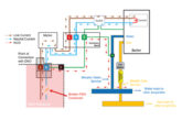
Therefore, as shown in Fig 1, to cater for switching and control devices electrical wiring in typical domestic premises may require the installation of a three-core and cpc PVC insulated and sheathed cable for the switch drops, rather than the traditional twin and earth cable.
 Additionally, deeper back boxes than the traditional 15 mm switch box may be required to accommodate the additional control module associated with the switch or dimmer. Irrespective of whether cables are concealed in the walls or not, AC circuits that supply luminaires in domestic premises should be provided with additional protection by an RCD having a rated residual operating current not exceeding 30 mA (Regulation 411.3.4 refers).
With the exception of certain control devices for lighting circuits, such as contactor control circuits, a single-pole functional switching device should not be placed in the neutral conductor (Regulation 463.1.2 refers). Whilst various types of electronic dimming devices are available to control lighting levels within rooms and areas of premises, the importance of providing appropriate switching arrangements for lighting circuits should not be overlooked (Regulation 559.5.1.207).
Although lighting circuits should be wired to provide the user with the flexibility to switch off (manually or automatically) a proportion of the lights when they are not needed, it is not uncommon to encounter switching arrangements that provide minimal flexibility.
Indeed, even the benefits of energy efficient lighting can be significantly undermined by inflexible switching arrangements. One example of this is ‘all or nothing’ arrangements where the luminaires installed in a particular room or large area are controlled by a single switch.
Fixing of luminaires
Luminaires should be adequately supported by means such as chain, screws, conduit boxes or enclosures and, in all cases, consideration should be given to the recommendations of the manufacturer of the particular fixing device. Whichever means of fixing is used to support the luminaire it must be capable of carrying a mass of not less than 5 kg, and if the mass is greater than 5 kg the fixing means must be capable of supporting the luminaire (Regulation 559.5.2 refers).
For twin flexible cable, such as that used to connect a ceiling rose to the luminaire, the maximum mass that should be supported by the flexible cable is given in Table 4F3A of Appendix 4 of BS 7671.
Where a luminaire is to be fixed to a wall or ceiling, the weight of the luminaire and any associated accessories should be compatible with the structural capability of the ceiling, or the building fabric (as applicable) to which it will be fixed. Flexible cables must be installed between the fixing means and the luminaire where vibration or movement is to be expected (Regulation 522.7.2).
Suitable means shall be provided so that there is no undue mechanical strain placed on the conductors, terminals and terminations from any expected stresses during normal use (Regulation 526.6 refers).
This may be achieved by cord grips, stuffing glands or similar. Where a device for connecting the luminaire to the fixed wiring is not provided with the luminaire, one of the devices listed in Regulation 559.5.4 should be used.
Protection against thermal effects
The selection and erection of a luminaire should take into account the thermal effects of radiant and convected energy on the surroundings. Regulation 559.4.1 requires the following points to be taken into account:
● the maximum power dissipation of the lamps
● the fire-resistance of adjacent material
● the minimum distance to combustible materials, including material in the path of a spotlight beam
● the relevant markings on the luminaire.
Luminaires are required to comply with the relevant product standards and be installed taking account of the manufacturer’s instructions.
Where a product is not suitable for particular mounting or installation method, the manufacturer is required to indicate this on the luminaire and control gear (see also Regulations 422.3.1 and 422.4.2).
Table 55.3 of BS 7671 provides an explanation of BS EN 60598-1 symbols applicable to luminaires and controlgear (see also the note to Regulation 422.3.2). Where a luminaire is installed in a pelmet, the electrical installation designer is required to take steps to prevent adverse effects, such as fire risks, caused by the presence of the blinds or curtains, or their operation (Regulation 559.3.3).
For luminaires installed in a location where, due to the nature of processed or stored materials, there is a particular risk of fire, the relevant requirements of Section 422 of BS 7671 should be met.
Through wiring
Through wiring is permitted only if the luminaire is designed for such wiring (Regulation 559.5.3.1). The type of cable to be used must be selected in accordance with the temperature information on the luminaire or in the manufacturer’s instructions, if any, and as specified in Regulation 559.5.3.2.
Wherever possible, the luminaire should be connected so that cables of the fixed installation do not have to travel through the fitting past heat generating items, such as chokes, in order to connect to the terminal block.
If this is not possible, the cables should be routed away from heat-generating components and effectively secured in place. Where necessary, heat resisting sleeving or shielding should be employed to protect cables from the effects of heat and ultra violet (UV) radiation, generated by the luminaire or its lamps (Regulation 559.5.6).
Maintaining earth continuity
Steel conduit is commonly used to supply luminaires, and in some installations the conduit may serve as the circuit protective conductor (cpc) for the lighting circuits contained within it.
Where this is the case, great care needs to be taken to ensure that the cpc is not compromised if an existing light fitting is replaced.
In circumstances where earth continuity is lost there is a risk of the metal conduit attaining line-to-earth voltage under fault conditions (say, due to mechanical damage or insulation failure), and this voltage is likely to remain undetected and pose a risk of electric shock to persons coming into contact with the conduit.
Where a separate protective conductor is installed in the metallic conduit, it is still necessary to earth the conduit, which is an exposed-conductive-part. If a run of conduit is to be earthed at one point only, continuity must be maintained throughout the run.
If this is not done, each section of conduit would have to be connected to the internal protective conductor. One way to ensure earth continuity of the conduit is maintained is to fix the fittings to the conduit system using appropriately spaced conduit boxes, as shown in Fig 2.
 Where the protective conductor is formed by a metal enclosure such as a conduit, the earthing terminal of each accessory should be connected by a separate protective conductor to an earthing terminal incorporated in the associated box or enclosure (Regulation 543.2.7).
Reference should also be made to Regulation 411.3.1.1 where a protective conductor must be run to and terminated at each point in wiring and at each accessory except a lampholder having no exposed-conductive-parts.
Stroboscopic effects
Stroboscopic effects can give a misleading impression of moving parts being stationary or slower moving than is the actual case, and as a result persons may be exposed to the risk of injury.
While such effects are generally associated with fluorescent luminaires operating at 50 Hz, other types of luminaires incorporating certain types of LEDs and electronic drivers have also been known to produce stroboscopic effects, and so electrical installation designers should take these effects into account when selecting luminaires (Regulation 559.9).
In order to avoid stroboscopic effects the designer may select discharge luminaires with high frequency control gear or, where available, distribute the lighting in the area concerned across all the phases of a three-phase supply.
Alternatively, industrial type filament lamps may be used to provide task lighting for a particular piece of equipment, such as a lathe.
Note: If luminaires are divided across three phases using a common neutral at least one device should be provided that simultaneously disconnects all line conductors (Regulation 559.5.5 refers).
Summary
Lighting installations should comply with the relevant requirements of Section 559 of BS 7671, which as outlined in this article requires, among other considerations, account to be taken of the provision of neutral conductors at switches and appropriate switching arrangements.
In addition, the replacement of a luminaire or similar maintenance should not compromise the continuity of any part of a metallic conduit system installed to supply luminaires.
Get more details about NICEIC registration by clicking here