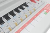
The primary purpose of a protective device is to protect the circuit from damage, and for such purposes Regulation 433.1.1 requires the operating characteristics of a device protecting a conductor against overload to satisfy the following conditions:
1: In ≥ Ib – The rated current or current setting of the protective device (In) should not be less than the design current (Ib) of the circuit.
2: In ≤ Iz – The rated current or current setting of the protective device (In) should not exceed the lowest of the current-carrying capacities (Iz) of any of the conductors of the circuit.
3: I2 ≤ 1.45 Iz – The current (I2) causing effective operation of the protective device should not exceed 1.45 times the lowest current-carrying capacity (Iz) of any of the conductors of the circuit.
Condition 1: In ≥ Ib
To avoid unwanted operation of the overload protective device when it is carrying the steady-state load current (Ib), condition 1 requires the rated current of the protective device (In) to be at least equal to Ib. However, due to the starting characteristics of the load a higher value of In may be necessary for certain loads (Regulation 533.2.1 refers)
In particular, certain types of electrical load such as discharge lighting, AC induction motors and transformers take a much higher current during starting than during normal operation. Consequently, a device protecting such a load must be carefully selected to ensure that it will not be operated by such ‘starting currents’.
As shown in Table 1, circuit-breakers designed to BS EN 60898-1 are classified into three distinct types – B, C, and D – according to the magnitude of current required to achieve automatic disconnection.
Condition 2: In ≤ Iz
This condition is intended to give protection under normal load conditions such that the steady state temperature of the conductors will not exceed the maximum admissible value (such as 70 ₀C for thermoplastic insulated conductors).
This is achieved by requiring the conductors to have suffcient current carrying capacity (Iz) to carry the rated current of the circuit protective device (In).
Condition 3: I2 ≤ 1.45 Iz
In circumstances when the circuit is subjected to an overload current, this condition is intended to ensure operation of the device within a time suitable to protect the insulation against damage from any high conductor temperatures caused by the overload current.
Small overloads of long duration
Regarding conditions 1 and 2, it is important that the circuit is designed so that small overloads of long duration are unlikely to occur (Regulation 433.1 refers). In other words, care should be taken that the amount of simultaneously operating load connected to the circuit (Ib), and the current rating of the conductors (Iz) and protective device (In), are such that there is unlikely to be a prolonged overload current lower than the current causing effective operation of the protective device (I2).
Meeting the requirement of condition 3
Provided the requirements of conditions 1 and 2 are met, the requirement of condition 3 is deemed to be met where the protective device is a type (gG) fuse to BS 88-2, a fuse to BS 88-3, a circuitbreaker to BS EN 60898 or BS EN 60947-2, or an RCBO of any type to BS EN 61009-1 (Regulation 433.1.201 refers).
Where the protective device is a semienclosed (rewireable) fuse to BS 3036, the requirement of condition 3 is met where In does not exceed 0.725 times the current-carrying capacity of the circuit conductors (Iz), provided the requirementsof conditions 1 and 2 are also met (Regulation 433.1.202 refers). This is to compensate for the high value of I2 of a BS 3036 fuse, which can be up to 2 × Iz.
For cables either buried directly in the ground or buried in ducts where currentcarrying capacity is based on an ambient temperature of 20 °C, compliance with condition 3 is afforded where In does not exceed 0.9 times Iz, provided the requirements of conditions 1 and 2 are also met. Regulation 433.1.203 refers.
Cable sizing procedures in Appendix 4 of BS 7671
Section 5 of Appendix 4 in BS 7671 lays out the procedure for determining the size of live conductors that will generally give compliance with the requirements of Regulations 433.1.1 to 433.1.203, discussed in this article.
Where overcurrent protective devices other than the fuses and circuit-breakers referred to in Regulations 433.1.201 and 433.1.202 are used, such as a thermal overload protective device in a motor circuit, it will be necessary for the electrical installation designer to refer to the device characteristics in order to ensure compliance with all aspects of Regulation 433.1.1.
Omission of overload protection devices
The omission of an overload protective device is permitted for both general and safety purposes. The installation of an overload protective device may not be needed for the general situations detailed in Regulation 433.3.1.
In addition, Regulation 433.3.3 permits the omission of overload protective devices for circuits supplying current using equipment where disconnectionof the device could result in danger or damage. For example, the unexpected disconnection of the supply to the lifting magnet shown in Fig 2 would cause the unintended release of the object without warning.
Where overload protection is omitted provision of an overload alarm should be considered.
For information about the NICEIC Approved Contractor or Domestic Installers schemes, visit www.niceic.com


